In the world of precision metal manufacturing, CNC machining is the cornerstone of quality, accuracy, and repeatability.
Among the most common CNC processes are turning and milling, each offering unique advantages depending on part geometry and production goals.
This article explores their key differences, applications, cost implications, and performance data, helping you choose the right method for your next project.
Understanding CNC Turning
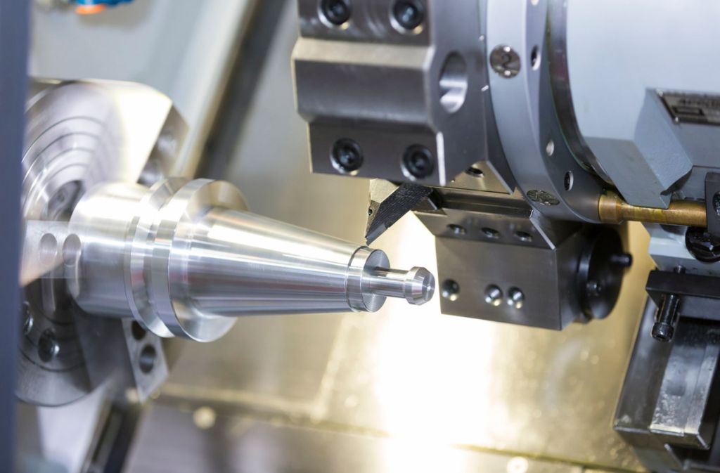
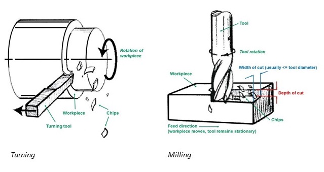
CNC turning involves a rotating workpiece and a stationary cutting tool. The lathe removes material from the surface to form cylindrical shapes such as shafts, bushings, and threaded components.
How It Works
-
The workpiece spins at high speed (up to 4000 RPM).
-
The cutting tool moves along linear axes (X and Z).
-
Material is sheared off in layers until the desired dimensions are reached.
Common Applications:
-
Automotive shafts
-
Bearing housings
-
Medical pins and rods
Typical Machining Parameters
| Parameter | Typical Range | Unit | Notes |
|---|---|---|---|
| Spindle Speed | 500–4000 | RPM | Based on material type |
| Feed Rate | 0.05–0.3 | mm/rev | Lower for hard metals |
| Cutting Depth | 0.2–2.0 | mm | Depends on part size |
| Tolerance | ±0.005 | mm | High precision for round features |
| Surface Finish | Ra 0.8–1.6 | µm | Smooth turned finish |
Advantages:
-
Excellent for symmetrical parts
-
High repeatability for mass production
-
Lower tooling costs per part
Illustration: A diagram showing a rotating metal rod with a stationary carbide cutting tool removing material.
Understanding CNC Milling

Unlike turning, CNC milling uses a rotating cutting tool that moves across a stationary or movable workpiece. It is ideal for flat, angled, and complex 3D parts.
How It Works
-
The cutting tool spins on multiple axes (X, Y, Z).
-
The workpiece remains fixed or moves along programmed paths.
-
Material is cut away layer by layer, producing intricate geometries.
Common Applications:
-
Aerospace brackets
-
Engine housings
-
Precision molds and dies
Typical Machining Parameters
| Parameter | Typical Range | Unit | Notes |
|---|---|---|---|
| Spindle Speed | 1000–18000 | RPM | Higher for aluminum or plastic |
| Feed per Tooth | 0.02–0.2 | mm/tooth | Controlled by cutter type |
| Tool Diameter | 1–25 | mm | Affects cut width and speed |
| Tolerance | ±0.01 | mm | Slightly lower than turning |
| Surface Finish | Ra 0.4–1.2 | µm | Can achieve mirror finishes |
Advantages:
-
Ideal for flat and contoured surfaces
-
Handles complex geometries and cavities
-
Flexible for multi-axis operations
Illustration: A 3-axis CNC mill removing material from an aluminum block to form a bracket.
CNC Turning vs. Milling — Technical Comparison

| Feature | CNC Turning | CNC Milling |
|---|---|---|
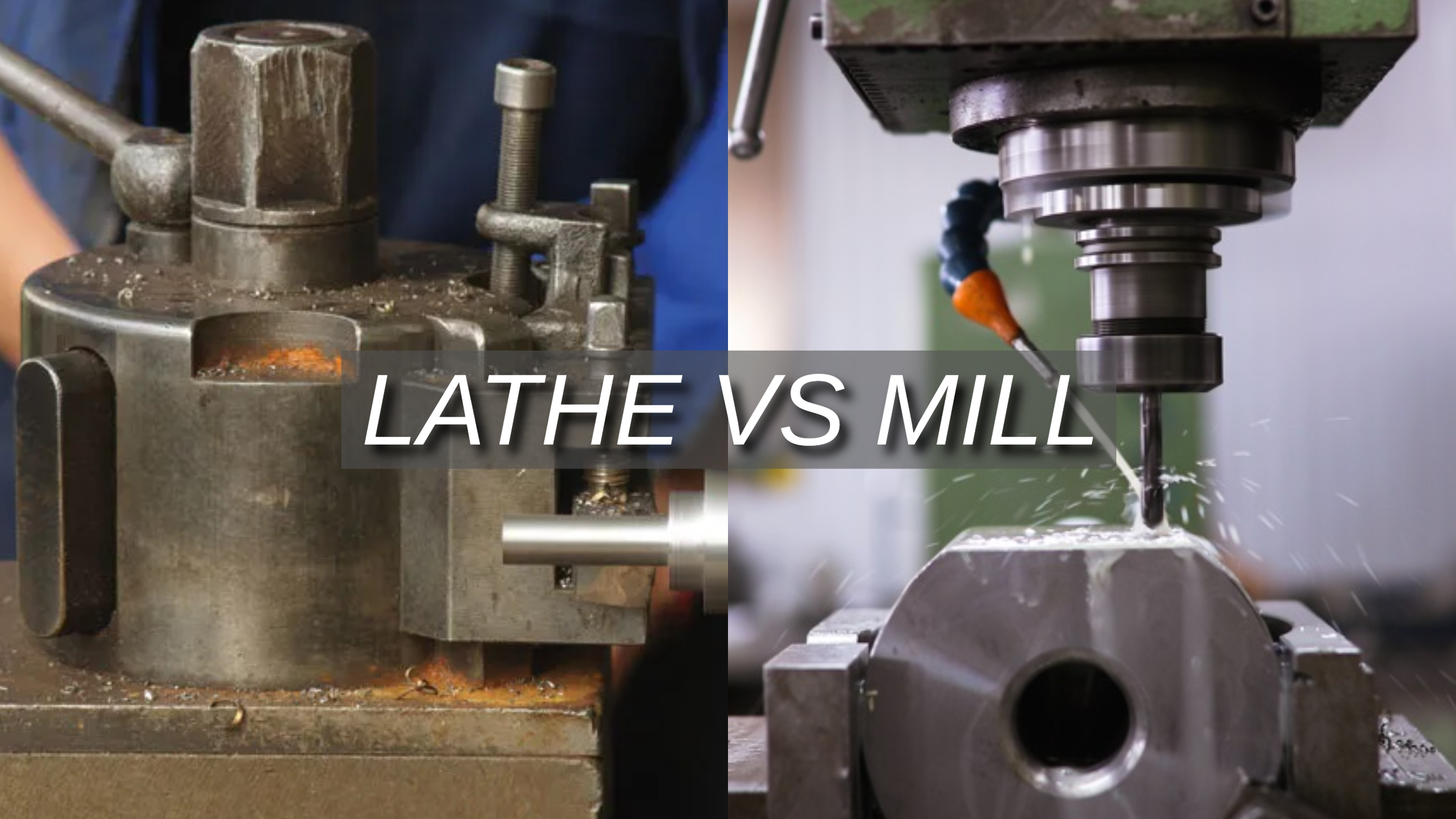
| Workpiece Motion | Rotates | Stationary or linear motion |
| Tool Motion | Linear | Rotational + linear |
| Best For | Cylindrical parts | Flat, angled, or 3D parts |
| Accuracy | ±0.005 mm | ±0.01 mm |
| Surface Finish | Ra 0.8–1.6 µm | Ra 0.4–1.2 µm |
| Material Removal Rate | High for round parts | Moderate |
| Setup Time | Low | Higher |
| Cost per Part | Low for volume | Moderate for prototypes |
| Ideal Materials | Steel, brass, copper | Aluminum, titanium, plastic |
Illustration: Split image comparing a lathe and a milling center with labeled motion arrows.
Choosing the Right Process
Selecting between CNC turning and milling depends on several key factors:
| Factor | Recommended Process | Reason |
|---|---|---|
| Round / Cylindrical Shapes | Turning | Efficient for rotational symmetry |
| Flat / Complex Shapes | Milling | Greater geometric flexibility |
| High Volume, Simple Parts | Turning | Faster cycle time |
| Prototyping, Complex Features | Milling | Multi-axis capability |
| Tight Tolerances | Turning | Consistent dimensional accuracy |
| Budget Constraints | Turning | Lower setup and per-part cost |
Tip: Many parts require both operations — turning for the outer profile and milling for holes or slots.
Hybrid Machining: When Turning and Milling Combine
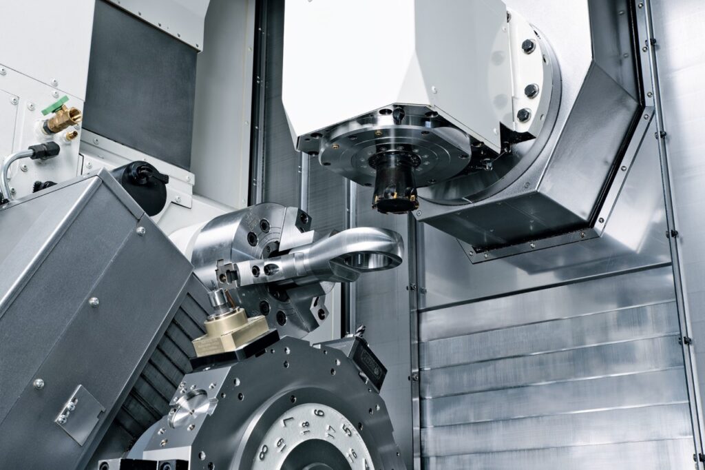
Modern mill-turn centers integrate both processes in one machine setup.
This hybrid approach reduces handling, setup time, and cumulative error, especially for complex metal components.
Example:
A motor shaft requiring both round diameters and milled flats can be completed in a single setup.
| Process | Setup Count | Total Time (min) | Dimensional Deviation (mm) |
|---|---|---|---|
| Separate Turning + Milling | 2 | 65 | ±0.03 |
| Combined Mill-Turn | 1 | 42 | ±0.01 |
Result: A 35% reduction in machining time and higher geometric accuracy.
Illustration: A mill-turn center working on a cylindrical part with side-milling operations.
Cost and Production Efficiency
| Process | Setup Cost ($) | Per-Part Cost (100 pcs) | Lead Time | Cost Efficiency |
|---|---|---|---|---|
| CNC Turning | 80–150 | 3.00–5.00 | 1–2 days | Excellent for round parts |
| CNC Milling | 120–250 | 5.00–9.00 | 2–4 days | Ideal for prototypes |
| Mill-Turn | 200–300 | 4.50–7.00 | 2–3 days | Balanced speed and precision |
Observation:
For large volumes of simple parts, turning is 40–60% more cost-efficient.
For complex parts, milling or hybrid machining offers greater design freedom.
Real-World Case Study: Automotive Valve Body
| Process | Material | Cycle Time | Parts/Day | Dimensional Accuracy | Cost per Unit |
|---|---|---|---|---|---|
| Turning | Aluminum 6061 | 4 min | 180 | ±0.005 mm | $4.20 |
| Milling | Aluminum 6061 | 7 min | 95 | ±0.01 mm | $7.80 |
| Mill-Turn | Aluminum 6061 | 5 min | 145 | ±0.007 mm | $5.10 |
Result: The mill-turn process achieved a balance of speed, precision, and cost, ideal for mid-volume automotive production.
Illustration: An automotive valve body being machined with both lathe and milling tools.
Conclusion
Both CNC turning and milling are vital to precision manufacturing — but their efficiency depends on your part geometry and production needs.
-
Choose turning for cylindrical, high-volume parts.
-
Choose milling for complex, flat, or contoured designs.
-
Consider mill-turn machining for the best of both worlds — fewer setups, higher accuracy, and reduced lead time.
By partnering with a professional CNC machining service provider, you can ensure optimal process selection, material efficiency, and part performance.
FAQs
What is the main difference between CNC turning and milling?
CNC turning rotates the workpiece while the cutting tool remains stationary, ideal for cylindrical parts.
CNC milling rotates the cutting tool and keeps the workpiece fixed, perfect for flat or complex geometries.
Which process is more accurate — turning or milling?
CNC turning generally provides higher dimensional accuracy (±0.005 mm) for round features, while milling offers ±0.01 mm, better for intricate shapes.
What materials are best for CNC turning?
Common materials include stainless steel, brass, aluminum, copper, and titanium — all suitable for producing shafts, bushings, and pins.
What materials are best for CNC milling?
Aluminum, titanium, steel, and engineering plastics (POM, ABS, Nylon) are often used for brackets, housings, and precision plates.
Which process is faster?
For cylindrical parts, CNC turning is usually 30–50% faster due to high spindle speeds and continuous cuts. Milling takes longer for complex tool paths.
Is milling more expensive than turning?
Typically yes. Milling requires more setup time, multi-axis tools, and slower cycle times, while turning is more cost-efficient for high-volume runs.
Can a part require both turning and milling?
Yes. Many components, such as valve bodies or motor shafts, need turning for the outer shape and milling for holes, flats, or slots.
What is a mill-turn machine?
A mill-turn center combines both processes in one setup. It can perform turning, drilling, and side-milling, reducing handling time and improving accuracy.
How do I choose the right process for my part?
-
Choose turning → if the part is round or tubular.
-
Choose milling → if the part has flat surfaces or complex geometry.
-
Choose hybrid (mill-turn) → if the part combines both.
What tolerance or surface finish can I expect?
| Process | Typical Tolerance | Surface Finish (Ra) |
|---|---|---|
| CNC Turning | ±0.005 mm | 0.8–1.6 µm |
| CNC Milling | ±0.01 mm | 0.4–1.2 µm |
Which industries use turning and milling most often?
Both are widely used in automotive, aerospace, medical devices, electronics, robotics, and energy sectors for high-precision metal parts.
How can I reduce machining costs?
-
Simplify geometry where possible
-
Use standard material stock sizes
-
Relax non-critical tolerances
-
Combine turning and milling in one setup