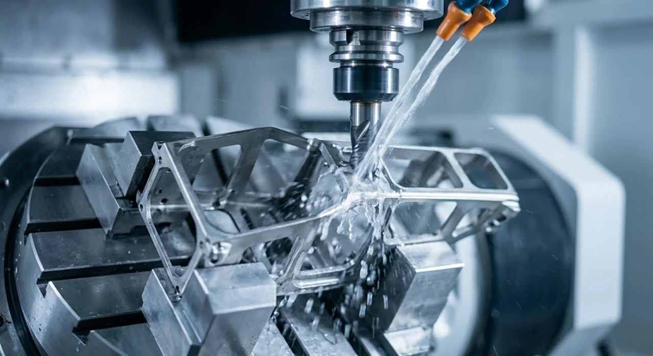
If you look at aerospace CAD models from the early 2000s and compare them to today’s blueprints, one thing becomes immediately obvious: the weight-saving demands have become extreme. Housings, brackets, and structural ribs that used to be beefy are now being engineered with wall thicknesses dipping well below 0.040″ (1 mm).
Because of its phenomenal strength-to-weight ratio, Grade 5 Titanium (Ti-6Al-4V) is the mandatory material for these flight-critical components. But any machinist who has spent time on the shop floor will tell you the ugly truth: when you try to machine thin titanium walls, they warp, bow, and scream.
When we set up our manufacturing lines at BOONA back in 2004, solving Ti-6Al-4V thin-wall distortion was one of the biggest hurdles we had to clear to earn our aerospace contracts. If you are tired of your current supplier throwing your expensive titanium billets into the scrap bin, here is the unfiltered reality of why thin walls fail, and the exact CAM strategies we use to hold them to tolerance.
The Physics: Why Thin Titanium Walls Collapse
You cannot bully a thin titanium wall into submission. It will fight back every single time due to two inherent material properties:
1. The “Springback” Effect
Titanium has a surprisingly low modulus of elasticity (roughly 114 GPa, compared to steel at ~200 GPa). In machinist terms, it is “springy.” When a carbide endmill engages a 0.040″ wall, the physical cutting force pushes the metal away from the tool. The cutter moves past the geometry, the wall springs back to its original position, and suddenly your perfectly programmed part is heavily oversized.
2. Localized Thermal Expansion
Titanium is a thermal insulator, meaning it does not transfer heat into the chip. The extreme heat stays right at the cutting zone. When you are machining a massive block, this heat burns the tool. But when you are cutting an ultra-thin wall, that localized section of metal superheats and physically expands into the cutting tool. The machine removes the expanded material, and when the part finally cools down, your wall is dangerously undersized.
Shop Floor Solutions: Changing the CAM Approach
To produce reliable precision titanium parts, you have to throw out standard machining practices. You cannot simply rough out a deep pocket, drop a long finishing tool in, and profile the entire wall in one shot. The vibration will shatter the tool or destroy the wall.
The “Step-Down” (Waterline) Support Strategy
We utilize a balanced waterline approach. Instead of machining one side of the wall completely to the floor, we machine the inside and outside simultaneously in alternating Z-level steps. We drop down 0.100″ on the inside, shift to the outside and drop 0.100″, and step our way down. This ensures that the fragile top edge of the wall is constantly supported by the thick, unmachined bulk material directly beneath it.
Mandatory Climb Milling
Conventional milling on a thin titanium wall is a guaranteed failure. It causes the tool to rub before biting, which pushes the wall hard and injects massive friction heat. For all aerospace titanium CNC machining, we strictly use climb milling. This shears the material cleanly and directs the cutting pressure parallel to the wall, keeping deflection to an absolute minimum.
The Thin-Wall Parameter Matrix
To stop deflection, you have to drastically reduce tool pressure. Here is a look at the actual baseline parameters our programmers use when setting up delicate features for our Grade 5 titanium machining services:
| Machining Parameter | Standard Ti-6Al-4V Block | Thin-Wall Ti-6Al-4V Target (<0.050″) | The Shop-Floor Reality |
| Radial Engagement (Ae) | 10% – 15% | Under 5% | Keeping the step-over tiny drastically reduces the physical force pushing against the wall, killing the “springback” effect. |
| Spindle Speed (SFM) | 120 – 150 SFM | 100 – 120 SFM | Lowering the RPM prevents the ultra-thin cross-section of metal from superheating and expanding. |
| Finishing Stock Left | 0.010″ | 0.003″ – 0.005″ | Leaving too much stock pushes the wall over. Leaving too little causes the tool to rub and work-harden the surface to glass. |
| Coolant Strategy | 1,000 PSI Through-Spindle | 1,000 PSI HPC + Flood | HPC clears chips so they don’t wedge and crack the wall, while heavy flood coolant keeps the overall part thermally stable. |
Workholding and Stress Relief: The Final Defense
Even if your CAM programming is flawless, if the raw billet holds internal forging stresses, the wall will bow like a banana the second you open the vise jaws.
The 0.020″ Thermal Bake
For flight-critical custom CNC machining for aerospace, we never rough and finish a part in the same shift. We rough the entire geometry, leaving precisely 0.020″ of material on the thin walls. We then pull the part from the machine and run it through a vacuum furnace stress-relief cycle. This bakes out the internal mill stresses. When it goes back into our 5-axis machines for finishing, the material is completely dead, stable, and ready to hold a tight tolerance.
Sacrificial Support and Potting
Standard machine vises will easily crush a hollowed-out aerospace housing. We design custom soft jaws that hug the 3D geometry. For extreme cases, we will fill the roughed-out pockets with rigid machining wax (potting). This wax acts as a solid backing during the final finishing cuts, preventing harmonic chatter. Once the part is done, we simply melt the wax out in hot water.
Stop Compromising on Aerospace Tolerances
Machining thin-wall Ti-6Al-4V isn’t a dark art, but it is an exact science of thermal management and tool pressure control. It requires rigid equipment, advanced workholding, and an engineering team that has made all the expensive mistakes so you don’t have to.
If your supply chain is returning parts with chatter marks, bowed walls, or missed dimensions, take a look at our dedicated Titanium CNC Machining Services page to see our setup.
Don’t let thin-wall distortion delay your assembly line. Send your 3D CAD files to the engineering team at BOONA today, and we will provide a comprehensive, free Design for Manufacturability (DFM) review and a hard quote within hours.
FAQs
Why do my thin titanium walls measure in-tolerance on the machine, but fail CMM inspection the next day?
You are getting caught in the thermal expansion trap. When you take a finishing pass on a 0.030″ wall, that thin cross-section heats up instantly. It expands. Your machinist probes it while it’s still clamped in the machine, and it reads perfectly. Overnight, the part cools down, shrinks, and suddenly your wall is undersized. You must flood the part with coolant to completely normalize the material temperature before pulling any final measurements.
To lower cutting pressure on a delicate wall, shouldn’t we just use the smallest endmill possible?
Actually, no. That is a classic amateur CAM programming mistake. If you use a tiny tool, the tool itself deflects instead of the part. You end up with a tapered wall (thicker at the bottom, thinner at the top). You want to use the largest, most rigid core diameter endmill that will physically fit the corner radius of your pocket, combined with a microscopically small radial step-over (Ae). Rigid tool, light bite.
My current supplier’s parts have terrible chatter marks near the bottom of deep, thin walls. How do you prevent that?
Chatter on deep titanium walls is a harmonics nightmare. Once you machine the pocket out, the thin wall basically acts like a tuning fork. If you use a standard endmill, the vibrations sync up and destroy the surface finish. We fix this by using premium variable-pitch, variable-helix endmills that break up the harmonic frequencies. If the wall is still screaming, we fill the cavity with rigid machining wax (potting) to make the wall temporarily solid, finish the outside, and then melt the wax out.
The vacuum stress-relief cycle adds lead time. Can we skip it to get the parts faster?
Only if you want to pay for scrap. Look, if the wall is thick and beefy, we can manage the stress through balanced machining (the flip-flop method). But if you are asking for a flight-critical 0.040″ housing, skipping the thermal bake is rolling the dice. The raw billet’s internal forging stress will warp the part the second we unclamp the soft jaws. It is always cheaper and faster to bake the part once than to machine it twice.
What is the absolute thinnest wall you can reliably machine in Grade 5 Titanium?
It depends heavily on the height of the wall (the depth-to-thickness ratio). As a general shop rule, we routinely hold 0.030″ (0.76mm) walls. We can go down to 0.015″ or 0.020″ if the wall is very short or supported by intersecting ribs. But we don’t guess. If you send us your 3D model and the geometry is physically impossible to cut without chattering to pieces, our engineering team will tell you straight up during the DFM phase and suggest where to add temporary support ribs.