A prototype can look perfect on a desk and still fail the first time someone snaps it into an assembly.
That happens more often than people admit.
A housing fits in CAD. The printed version looks clean. Then the clip breaks. The screw boss cracks. A small bracket twists under load. Or the customer says, “This feels nothing like the final part.”
That is exactly where MJF vs FDM 3D printing becomes more than a process comparison. It becomes a product-development decision.
FDM can be excellent for fast, low-cost design checks, larger housings, ergonomic models, rough-fit brackets, and early internal reviews. MJF usually becomes the better choice when the prototype has to work harder — snap fits, small clips, nylon-like housings, detailed brackets, repeated handling, or small-batch functional testing.
Neither process is “better” all the time. That would be too simple, and frankly, not very useful.
The better question is this: what does the prototype need to prove?
If the answer is “shape and fit,” FDM may be enough. If the answer is “strength, detail, and functional behavior,” MJF often deserves the first look. And if the part needs a tight bore, real stock material, or a machined sealing face, 3D printing may not be the right process at all.
What FDM Does Well for Functional Prototype Parts
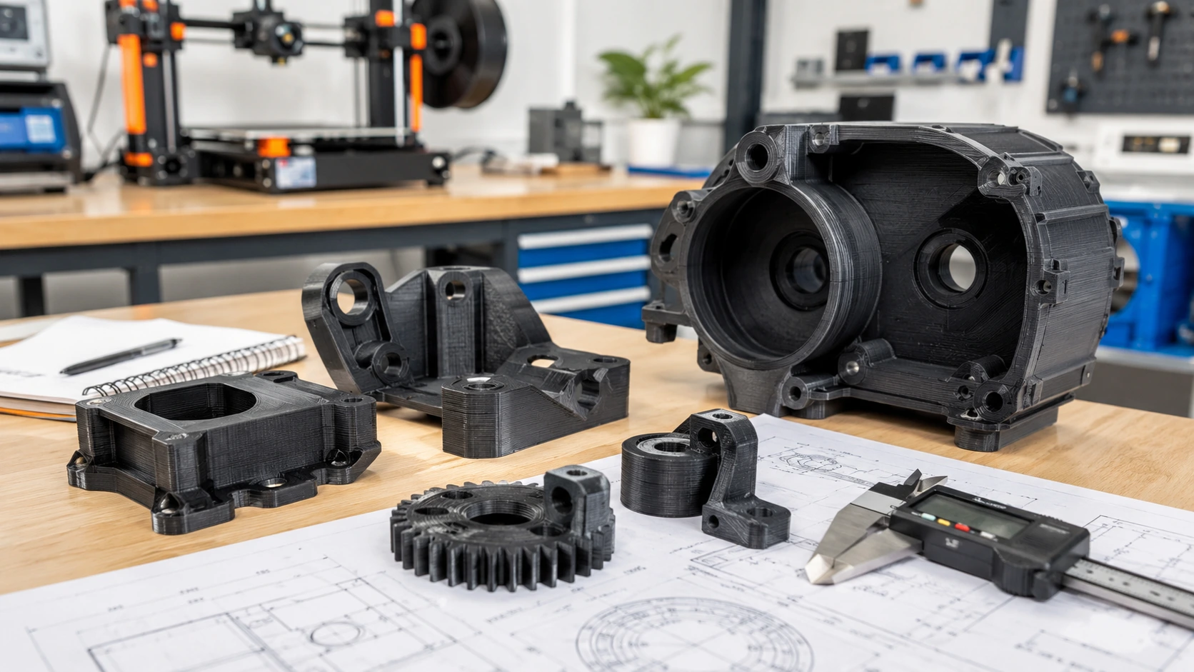
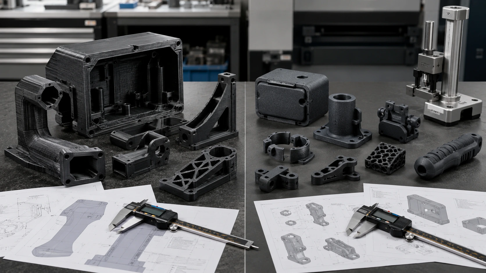
FDM is the process most people picture when they hear “3D printing.” A heated nozzle lays down thermoplastic filament, layer by layer, until the part takes shape. It is direct, flexible, and easy to understand.
That familiarity is one reason FDM prototype parts are still everywhere in product development.
For early-stage work, FDM is hard to beat. Need a large enclosure to check board clearance? A handheld housing to judge grip size? A quick fixture for an assembly trial? FDM can usually get the team moving fast without burning budget on a more advanced process too early.
The material range is also useful. PLA works for simple concept models. PETG gives better toughness for shop-floor prototypes. ABS and ASA can support housings and general functional checks. PC and nylon can be used when the part needs more strength or heat resistance, though print conditions become more demanding. TPU is useful when the prototype needs flexibility.
Still, FDM has a weakness engineers must respect: layer bonding.
A part may be strong in one direction and surprisingly weak in another. If a clip, hook, tab, or screw boss loads across the layer lines, it can split before the material itself has a chance to perform. We’ve seen this many times in prototype reviews — the design gets blamed first, but the real issue is print orientation.
FDM works best when the team understands the load path and accepts the surface finish. For many early functional checks, that is perfectly fine.
Where MJF Becomes the Better Functional Prototype Process
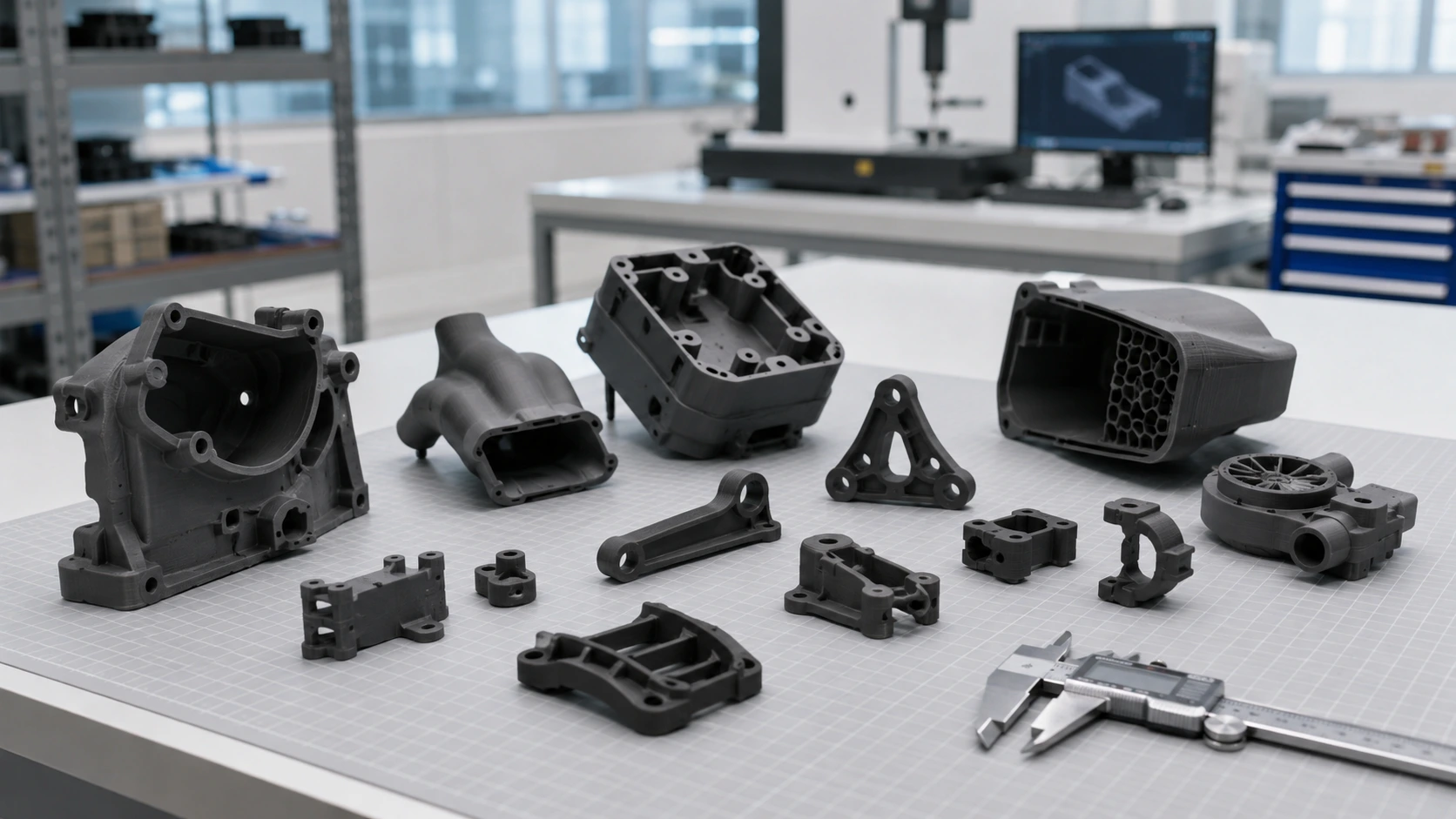
MJF, or Multi Jet Fusion, takes a different route. Instead of extruding filament, it builds parts from nylon powder using fusing agents and controlled heat. The surrounding powder supports the part during printing, so MJF can handle many geometries that would be awkward or messy in FDM.
This is where MJF 3D printed parts start to feel more “engineering-grade.”
MJF PA12 parts typically provide more balanced strength than FDM parts. They are not magic, and they are not the same as injection molded nylon, but they usually behave better when the prototype needs to survive repeated handling, snap-fit testing, light loading, or assembly cycles.
Small clips. Thin housings. Internal ducts. Compact brackets. Lattice structures. Wearable device shells. These are places where MJF often earns its cost.
Another advantage is batch efficiency. Many small parts can be nested together in the powder bed, which makes MJF useful for low-volume 3D printed parts. If a team needs 20 small brackets or 40 clip samples, MJF may price better than expected because the build volume is used efficiently and there is usually no support-removal labor.
Technical data helps set expectations. MJF PA12 commonly uses around 0.08 mm layer thickness, with typical published tensile strength around 48 MPa and tensile modulus around 1,700 MPa, depending on supplier and process conditions. Standard accuracy is often listed around ±0.3% with a minimum tolerance band such as ±0.3 mm. Real parts still depend on geometry, wall thickness, orientation, post-processing, and inspection method.
That last sentence matters. Data sheets are a starting point, not a guarantee.
MJF vs FDM 3D Printing: Practical Comparison for Buyers
A simple table helps, but it should be read with context. A large FDM housing and a small MJF clip are not competing on the same terms.
| Factor | FDM | MJF |
|---|---|---|
| Build method | Melted filament extrusion | Powder-bed fusion nylon process |
| Common materials | PLA, ABS, PETG, ASA, PC, nylon, TPU | PA12, PA11, glass-filled PA12, TPU options |
| Strength behavior | Highly dependent on layer direction and orientation | More balanced strength for many functional parts |
| Surface finish | Visible layer lines | Fine matte, slightly grainy texture |
| Support structures | Often needed | Usually not needed |
| Internal channels | Limited by support removal | Much easier to design |
| Best use | Early concepts, large parts, low-cost checks | Functional nylon prototypes, clips, small batches |
| Typical concern | Layer splitting, visible lines, support marks | Higher cost for large solid parts |
For MJF vs FDM 3D printing, this is the practical split: FDM helps teams learn quickly; MJF helps teams test function more seriously.
That is why many prototype programs use both. The first enclosure may be FDM. The second version, once the design starts to stabilize, may move to MJF. Later, if the part requires tighter fit, a controlled finish, or real engineering stock, CNC machining may enter the process.
For broader process selection, Boona 3D printing service is a useful starting point for comparing prototype manufacturing options.
Strength and Accuracy: The Difference Shows Up During Testing
Strength claims can mislead buyers if they ignore print direction.
FDM parts are strongly affected by raster direction, wall count, infill, layer height, nozzle temperature, cooling, material drying, and build orientation. A bracket printed flat may survive a test. The same bracket printed upright may split along the layer lines. That is not a rare failure mode. It is normal FDM behavior.
MJF generally reduces that directional weakness. The mechanical behavior is still not perfectly isotropic, but it is often more predictable for functional prototype parts. That gives engineers more confidence when testing clips, housings, internal brackets, and small load-bearing features.
Accuracy follows the same logic. FDM can be accurate enough for large fit checks, but small holes, sharp tabs, and thin walls may need extra clearance. MJF usually handles smaller features more consistently, although tight bores, bearing fits, precision threads, and sealing faces may still need post-machining.
Here is the decision we often use in practice:
| Requirement | Better Starting Process | Practical Note |
|---|---|---|
| Fast fit check | FDM | Good for early shape validation |
| Snap-fit feature | MJF | Better nylon behavior and detail |
| Large low-load housing | FDM | Usually more cost-effective |
| Small functional bracket | MJF | Better consistency and finish |
| Tight bore or dowel hole | CNC machining | Printing alone may not be enough |
| Production-like nylon prototype | MJF | Good bridge before tooling |
In my experience working with manufacturers, the biggest prototype mistake is not choosing a “bad” process. It is choosing the right process for the wrong test.
A visual check and a functional test are different jobs.
Surface Finish and Design Freedom
FDM has a signature look. Layer lines. Support marks. Sometimes small seam lines. These may be acceptable on an internal fixture or early engineering sample, but they can distract during a customer demo or ergonomic review.
MJF gives a more uniform technical surface. It usually has a fine matte texture — not glossy, not injection molded, but cleaner and more consistent than most FDM surfaces. Parts can often be dyed, smoothed, painted, or coated depending on the requirement.
That said, I would not call MJF a cosmetic process by default. It is a functional process first. If the customer expects an injection-molded look, post-processing still matters.
Design freedom is where MJF has a clear advantage. FDM support structures can limit overhangs, internal channels, and fine mechanical features. Support removal may also leave marks on visible or functional surfaces.
MJF powder supports the part during the build, so designers can use more complex shapes: ducts, lattices, internal cavities, lightweight brackets, nested components, and organic geometry. For custom 3D printed prototype parts, that freedom can save redesign time.
FDM still wins when the geometry is simple, large, and low-risk. No need to overpay for complexity you do not need.
For finishing decisions, Boona surface finishing FAQ can help buyers think through sanding, painting, dyeing, smoothing, and other post-processing options.
Cost and Quantity: FDM Is Not Always Cheaper
FDM often looks cheaper at first, especially for one simple part. That is real. For a large rough-fit housing or an internal concept model, FDM is usually the economical choice.
But cost changes when geometry and quantity change.
MJF can become more attractive when the parts are small, detailed, complex, or ordered in batches. Powder-bed nesting allows many parts to share one build. Support removal usually does not add the same labor burden. A small MJF batch can sometimes beat a collection of FDM prints that require careful orientation, support cleanup, and rework.
The additive manufacturing market also reflects this shift toward functional work. Wohlers/ASTM reported that the AM industry grew 11.1% to $20.035 billion in 2023. Jabil’s 2023 survey found that 97% of respondents used 3D printing for prototyping, 75% for R&D, and 59% for production parts. Those numbers show something important: companies are no longer using 3D printing only for appearance models.
For fast iteration, Boona rapid prototyping service can support early development, and standard plastic 3D printed parts often move quickly when the design is ready and requirements are clear.
A practical cost rule: use FDM when learning is the priority. Use MJF when functional confidence is worth paying for.
A Real-World Example: Handheld Device Housing
A handheld inspection device gives a good example.
The first prototype only needed to answer basic questions. Does the PCB fit? Does the battery clear the ribs? Does the grip feel too thick? Can the cable exit where the designer planned? FDM was the obvious choice. It was fast, affordable, and flexible.
After three revisions, the housing shape became more stable. Then the team needed to test snap tabs, screw bosses, internal clips, and repeated assembly. The FDM samples started showing the usual weakness: a few clips broke along layer lines, and support marks affected one internal latch.
At that point, MJF PA12 made more sense.
The MJF housings gave cleaner clip geometry, better small-feature consistency, and a more realistic nylon-like feel. They still were not final production parts, but they were good enough to test function with more confidence.
Later, a few critical insert locations and mating surfaces still needed CNC machining. That was not a failure of MJF. It was the right process split: FDM for early shape learning, MJF for functional plastic testing, CNC for precision features.
💡 Pro Tip: Do not choose one process for the whole development cycle. Use FDM when the question is “Does it fit?” Use MJF when the question is “Will it work?” Use CNC machining when the question is “Will this feature pass inspection?”
When CNC Machining Beats Both MJF and FDM
There is a point where printing is no longer the best answer.
If a part needs a precision bore, a smooth sealing face, real PEEK stock, a tapped thread, a tight dowel hole, or controlled flatness, CNC machining may be the better starting process. Printed parts build layer by layer. CNC parts come from solid stock. That difference matters when material behavior and tolerance matter more than speed.
For example, a real PEEK prototype for a medical, semiconductor, or high-temperature assembly should usually be machined from PEEK stock. Printing it in another plastic may help check shape, but it will not prove the final material behavior.
| Requirement | Best Starting Process |
|---|---|
| Fast concept model | FDM |
| Functional nylon prototype | MJF |
| Small complex batch | MJF |
| Large enclosure fit check | FDM |
| Tight tolerance bore | CNC machining |
| Smooth sealing face | CNC machining |
| Real PEEK or PEI prototype | CNC machining |
| Production-like plastic test | MJF or CNC, depending on material |
For projects that move beyond printed prototypes, Boona plastic CNC machining and CNC machining service can support the transition into tighter, more material-specific parts.
RFQ Details That Help Suppliers Choose Correctly
A CAD file tells us the shape. It does not tell us the job.
That gap causes many prototype quoting mistakes.
If a part needs to survive 50 snap cycles, say so. If it only needs to sit on a table for a design review, say that too. If a small hole receives a dowel pin, the supplier should know before printing. If the part will see heat, chemicals, load, vibration, or repeated assembly, those details can change the process recommendation.
A strong RFQ for functional prototype parts should include the 3D CAD file, quantity, material preference, tolerance notes, surface finish expectations, color requirement, deadline, assembly conditions, and test purpose. If tolerances matter, include a 2D drawing.
One sentence can help a lot: “Functional prototype for snap-fit testing, 25 pieces, black nylon preferred, no cosmetic paint required.”
That is much better than a CAD file with no context.
For low-volume 3D printed parts, the best supplier recommendation usually comes from the test condition, not just the model geometry.
Conclusion: MJF vs FDM 3D Printing Depends on the Prototype’s Job
MJF vs FDM 3D printing is not a simple process battle. It is a practical engineering choice.
FDM works well when speed, size, and cost matter most. It is ideal for early fit checks, large housings, ergonomic models, simple brackets, and fast internal design reviews.
MJF becomes the better choice when the prototype needs stronger nylon behavior, finer features, snap-fit testing, support-free complexity, small-batch consistency, and a more production-like functional feel.
CNC machining takes over when the part needs real engineering stock, tight tolerance, smooth machined surfaces, threaded features, or critical functional geometry.
The smartest prototype path often uses more than one process. Learn fast with FDM. Test function with MJF. Machine the critical features when tolerance or material behavior matters.
Need help choosing the right manufacturing route for your prototype? Send your CAD files and application notes to Boona 3D printing service team. We can help review whether FDM, MJF, CNC machining, or a combined approach fits the part best.
FAQs
What is the main difference between MJF and FDM 3D printing?
MJF uses powder-bed fusion to make nylon parts, while FDM builds parts by extruding melted filament layer by layer. For functional prototypes, MJF usually offers better detail and more balanced strength, while FDM is often faster and cheaper for early fit checks.
Is MJF stronger than FDM for functional prototypes?
MJF is usually stronger than FDM when the part needs more balanced strength across different directions. FDM strength depends heavily on print orientation, layer bonding, wall thickness, and material choice, so it works best when the load direction is predictable.
When should I choose FDM instead of MJF?
Choose FDM when you need fast, lower-cost prototypes for size checks, ergonomic reviews, large housings, simple brackets, or early assembly tests. It is a practical option when fine surface finish and production-like nylon performance are not required.
When is MJF better for functional prototype parts?
MJF is better when the prototype needs stronger nylon performance, snap-fit features, small details, complex geometry, or small-batch consistency. It is often used after early FDM models prove the shape and the team needs a more serious functional test.
Which process has better surface finish, MJF or FDM?
MJF usually has a finer and more uniform matte surface than FDM. FDM parts often show visible layer lines and support marks, especially on curved or overhanging features. For cosmetic prototypes, both processes may still need post-processing.
Is MJF more expensive than FDM 3D printing?
MJF is often more expensive than FDM for simple one-off parts or large rough-fit models. However, MJF can be cost-effective for small complex batches because many parts can be nested in one powder-bed build and support structures are usually not required.
Can MJF or FDM replace CNC machining for prototypes?
MJF or FDM can replace CNC machining for some prototype parts, especially when speed and design iteration matter more than tight tolerances. CNC machining is still better for precision bores, threaded features, sealing faces, smooth machined surfaces, or real engineering stock materials.
What should I provide when requesting an MJF or FDM prototype quote?
Provide a 3D CAD file, quantity, material preference, prototype purpose, surface finish expectation, color requirement, deadline, and functional test conditions. If tolerances, inserts, threads, or assembly fits matter, include a 2D drawing so the supplier can recommend the right process.