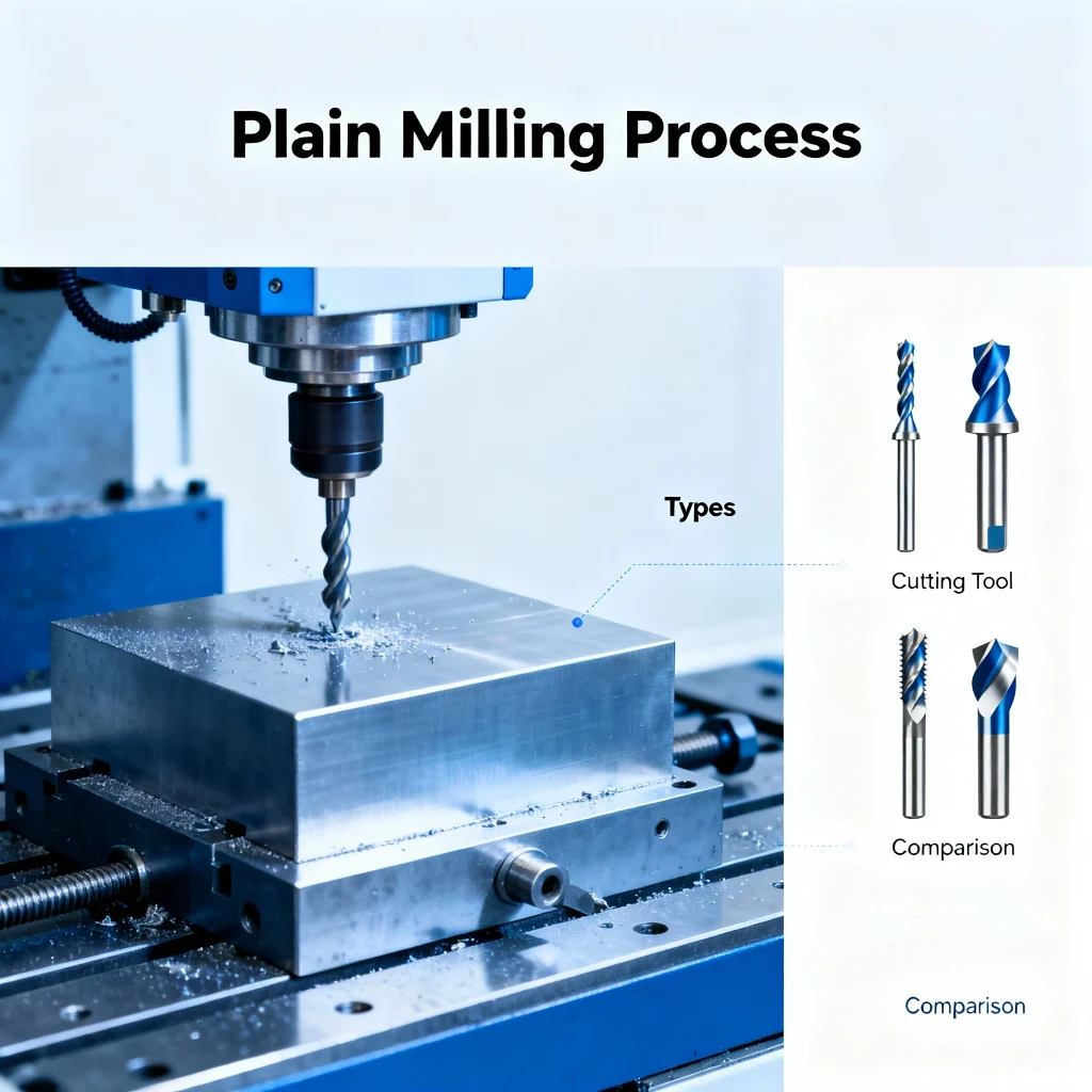
Plain Milling: Process, Types, Cutting Tools, and Comparison
Plain milling, also known as surface milling or face milling (in certain configurations), is a fundamental machining operation used to produce flat or contoured surfaces on a workpiece. In this article, we will present a structured overview of the plain milling process, its various types, cutting tool options, and comparisons of trade-offs. We will also reference Boona Prototypes’ milling capabilities to illustrate real-world context and provide an internal link for SEO benefits (see CNC Milling Services at Boona Prototypes).
I. Introduction
Plain milling is a widely used machining method in which a rotating cutter with multiple cutting edges removes material from the surface of a workpiece in order to create a flat or slightly contoured surface. It is especially common in applications such as flattening large faces, preliminary surfacing, or producing datum faces.
This article covers:
-
The plain milling process and underlying principles
-
Different types or modes of plain milling
-
Cutting tool designs and materials used in plain milling
-
Comparative analysis of trade-offs, including advantages/disadvantages
-
Practical parameter tables and tips
For a practical reference of an advanced CNC milling provider, see Boona Prototypes’ CNC milling services (3-axis, 4-axis, 5-axis) at their website: https://www.boona-prototypes.com/cnc-milling/
II. Plain Milling Process
2.1 Principle & Motion
In plain milling, either the workpiece or the cutter (or both) moves linearly while the cutter rotates. The cutting edges on the face of the cutter remove material by shearing action. The relative motion defines cut engagement, chip thickness, and tool engagement.
There are two principal modes: up milling (conventional milling) and down milling (climb milling), which differ by the direction of feed relative to cutter rotation.
2.2 Key Process Parameters
Some of the principal process parameters include:
| Parameter | Symbol / Abbreviation | Typical Units | Role / Effect |
|---|---|---|---|
| Cutting speed | vcv_c | m/min or ft/min | Surface speed of cutter relative to workpiece; affects temperature and tool life |
| Spindle speed | nn | rpm | Derived from vcv_c and cutter diameter ( n=1000 vcπDn = \frac{1000 \, v_c}{\pi D} in metric ) |
| Feed per tooth | fzf_z | mm/tooth or in/tooth | Governs chip load; too low causes rubbing, too high overloads teeth |
| Table feed / Linear feed | vfv_f | mm/min or in/min | = n×fz×zn \times f_z \times z, where zz is number of teeth |
| Axial depth of cut | apa_p | mm or in | Depth in the Z direction (i.e. how much thickness is removed) |
| Radial depth / width of cut | aea_e | mm or in | Width of engagement of cutter teeth |
| Metal removal rate (MRR) | mm³/min or in³/min | Q=ap×ae×vfQ = a_p \times a_e \times v_f |
The cutting forces (tangential, radial, axial) and power consumption depend on these parameters, the workpiece material, and tool geometry. Improper parameter choice may lead to excessive tool wear, chatter, or poor surface finish.
2.3 Force, Power & Chip Formation
-
Cutting forces: The tangential (main cutting) force is the dominant one; radial and axial forces also matter for stability and deflection.
-
Power: The required cutting power can be estimated as P=Ft⋅vc60,000P = \frac{F_t \cdot v_c}{60,000} (for suitable units), or via empirical formulas using specific cutting force constants.
-
Chip formation: Chip thickness varies along the cut as the cutter engages and disengages. Heat generation is concentrated in the shear zone and flank contact, so cooling/lubrication is often needed.
2.4 Machine Rigidity & Vibration Issues
Because plain milling often involves wide engagement and high cutting forces, machine rigidity, tool holding stiffness, fixture design, and avoidance of chatter are critical. Stability lobe diagrams are often used in advanced setups to choose cutting speeds and depths that avoid resonance.
III. Types / Variations of Plain Milling
3.1 Up Milling vs. Down Milling
-
Up milling (conventional milling): The cutter rotates against the feed direction; the chip starts thin and grows thicker. Less likely to pull the workpiece but results in rubbing at the start, higher tool wear, poorer surface finish in some cases.
-
Down milling (climb milling): The cutter rotates with the feed direction; chip starts thick then decreases. Better surface finish, lower cutting forces, but requires rigid and backlash-free drives to prevent workpiece pull.
3.2 Based on Cutter Geometry / Configuration
-
Face mills: Cut with the face of the cutter, often with replaceable inserts.
-
Slab mills: Long cylindrical cutters that remove material over a wide face.
-
End mills used in face mode: An end mill used in a “face milling” orientation to cut a broad face.
3.3 Based on Machining Axes
-
2-axis / 3-axis: Basic flat surface milling.
-
4-axis / 5-axis: Allows complex surfaces and multi-sided milling — as often offered by Boona Prototypes’ CNC milling services. Boona Prototypes
3.4 Based on Orientation / Application
-
Horizontal plain milling: Cutter axis horizontal, workpiece moves beneath.
-
Vertical plain milling: Cutter axis vertical, as in many modern machining centers.
3.5 Specialized Variants
-
Helical / ramp milling: Cutter engages gradually at an angle.
-
Trochoidal or high-efficiency milling: Paths planned to reduce radial engagement and keep chip thickness moderate.
IV. Cutting Tools for Plain Milling
4.1 Cutter Types
-
Face mills (indexable or solid)
-
Slab mills
-
End mills in face milling orientation
4.2 Tool Materials & Coatings
-
High-speed steel (HSS) — economical, moderate hardness
-
Carbide (cemented carbide) — much higher hardness, better wear resistance
-
Coated carbide (e.g., TiN, TiAlN, AlTiN, DLC, etc.) — to reduce friction, boost wear life
-
Advanced materials: CBN, ceramics, PCD/PCBN (for very hard materials)
4.3 Insert Geometry & Chip Breakers
Insert shape, chip breaker design, and edge preparation (hone, chamfer) all influence chip flow, cutting forces, and surface finish.
4.4 Cutter Geometry Parameters
-
Number of teeth / inserts z
-
Rake angle (positive, neutral, negative) — positive rake reduces cutting forces but may weaken edge; negative rake improves strength at cost of higher force
-
Relief / clearance angle
-
Helix / lead angle
-
Edge radius or hone
4.5 Tool Holding & Rigidity
A robust toolholder and minimal overhang are essential to reduce deflection, vibration, and ensure consistent finish and tool life.
4.6 Tool Life, Wear Modes & Failure
Typical wear modes include flank wear, crater wear, chipping, built-up edge (BUE), and coating delamination. Tool life is influenced by cutting speed, feed, depth of cut, material hardness, cooling, and chip evacuation.
V. Comparison & Trade-offs
5.1 Up Milling vs. Down Milling
| Aspect | Up Milling | Down Milling |
|---|---|---|
| Chip start thickness | Thin → thicker | Thick → thinner |
| Surface finish | Generally poorer | Better in many cases |
| Cutting force direction | Tends to push workpiece | Tends to pull workpiece (better contact) |
| Backlash sensitivity | Less demanding | More demanding (requires backlash-free drive) |
| Tool wear | More rubbing, possibly higher wear | Smoother entry, lower wear |
5.2 Plain Milling vs Other Milling Types
-
Plain vs slot milling: Slot milling cuts full width or narrow slots; plain milling often handles broader surfaces.
-
Plain vs profile / contour milling: Profile milling follows curves and edges; plain is mostly flat surfaces.
-
Plain vs end milling: End milling often handles complex 3D shapes, but in “face mode” an end mill can approximate plain milling.
5.3 Cutter Selection Trade-offs
-
More inserts → more teeth, higher feed per revolution but risk of interference
-
Coated vs uncoated: coatings add cost but often pay off in life
-
High-feed vs high-speed: high-feed tools optimize high throughput, high-speed tools push speed but may reduce tool life
5.4 Parameter Trade-offs
-
Increasing feed improves material removal rate (MRR) but increases forces and risk of tool overload
-
Increasing depth of cut also increases MRR but demands stronger machine / setup
-
Speed vs tool life: faster speeds shorten life; optimal speeds are often a compromise
-
Stability: aggressive cuts may excite chatter — need to balance between maximum removal and stable operation
5.5 Economic & Productivity Comparisons
-
MRR: Compare across methods
-
Tool cost per part: Includes tool life, number of inserts, downtime
-
Setup cost / machine utilization: Simpler operations reduce time overhead
VI. Practical Considerations & Sample Parameter Table
6.1 Material Effects
Different materials (aluminum, steel, titanium, plastics) require different speeds, feeds, and tool geometries.
6.2 Cooling / Lubrication
Flood coolant, minimum quantity lubrication (MQL), or high-pressure coolant can help reduce heat, improve chip evacuation, and extend tool life.
6.3 Fixture, Clamping & Rigidity
Secure clamping and minimal vibration are critical, especially in plain milling where large surfaces are involved.
6.4 Chatter Avoidance & Vibration Control
Use stability diagrams, reduce engagement, adjust cutting parameters or change tool overhang.
6.5 Surface Finish Optimization
Use finishing passes at lower depth/feed; fine edge geometry; proper tool path planning.
6.6 Tool Wear Monitoring
Regular inspection, tool offsets correction, adaptive control systems.
6.7 Example Table: Recommended Cutting Parameters
Below is a sample parameter table for plain milling (face milling) in common materials. These numbers are illustrative; in practice they must be adapted to tooling, machine, rigidity, coolant, etc.
| Workpiece Material | Cutter Dia (D) | Cutting Speed vcv_c (m/min) | Feed per Tooth fzf_z (mm/tooth) | Axial Depth apa_p (mm) | Radial Engagement aea_e (mm) |
|---|---|---|---|---|---|
| Aluminum 6061 | 50 mm | 200 | 0.10 | 2 | 20 |
| Steel (mild) | 50 mm | 120 | 0.06 | 1.5 | 15 |
| Stainless Steel | 50 mm | 80 | 0.04 | 1.0 | 10 |
| Cast Iron | 50 mm | 150 | 0.08 | 2.0 | 18 |
| Titanium alloy | 50 mm | 60 | 0.03 | 0.8 | 8 |
From these, one can compute:
-
Spindle speed n=1000 vcπDn = \frac{1000 \, v_c}{\pi D}
-
Table feed vf=n×fz×zv_f = n \times f_z \times z
-
MRR =ap×ae×vf= a_p \times a_e \times v_f
For example, for aluminum case:
-
n=1000×200π×50≈1273 rpmn = \frac{1000 \times 200}{\pi \times 50} \approx 1273\ \text{rpm}
-
If cutter has 4 inserts (z = 4): vf=1273×0.10×4=509.2 mm/minv_f = 1273 \times 0.10 \times 4 = 509.2\ \text{mm/min}
-
MRR = 2×20×509.2=20,368 mm3/min2 \times 20 \times 509.2 = 20,368\ \text{mm}^3/\text{min}
These parameter ranges are consistent with published cutting data charts (e.g. in Ingersoll’s cutting data tables) and general milling formula references.
IX. Summary & Conclusion
Plain milling is a versatile and essential machining operation for producing flat surfaces efficiently. The choice of process mode (up vs down), cutter design, parameter selection, and machine rigidity all play a critical role in achieving optimal results. In practice, high-precision OEMs and prototype houses (like Boona Prototypes) leverage multi-axis CNC milling (3-axis to 5-axis) to handle complex shapes and maintain tight tolerances. (See their CNC milling service offering: https://www.boona-prototypes.com/cnc-milling/)
Key takeaways:
-
Always balance productivity (MRR) with stability, tool life, and surface quality
-
Use appropriate tooling, coatings, and insert geometry tailored to material
-
Carefully choose speeds, feeds, depths, and widths of cut, and monitor for vibration
-
Maintain rigidity in machine, tool, and workholding
-
Constant iteration and fine adjustment in real job-shop conditions is often needed
FAQs
🔧 Frequently Asked Questions (FAQs) About Plain Milling
1. What is plain milling in machining?
Plain milling is a machining process where a rotating cutter removes material from the surface of a workpiece to create a flat or smooth finish. The cutter’s axis is usually parallel to the workpiece surface, and the process is often performed on horizontal or vertical milling machines.
2. What is the difference between plain milling and face milling?
Plain milling typically uses a cutter with its axis parallel to the surface being machined, removing material from wide, flat areas. Face milling, by contrast, uses a cutter whose axis is perpendicular to the surface, producing a smoother finish on large faces. However, in practice, both are closely related and sometimes overlap in function.
3. What are the main types of plain milling?
The two primary types are up milling (conventional milling) and down milling (climb milling):
-
Up milling: The cutter rotates opposite to the feed direction, providing a gradual chip start but more friction.
-
Down milling: The cutter rotates with the feed direction, providing better finish and longer tool life but requiring a rigid setup.
4. What cutting tools are used in plain milling?
Common tools include face mills, slab mills, and end mills. These tools may use HSS (High-Speed Steel), carbide, or ceramic inserts, often with advanced coatings like TiN, TiAlN, or DLC for better wear resistance and heat control.
For industrial examples of modern tooling used in rapid prototyping and production, visit Boona Prototypes CNC Milling Services.
5. What parameters affect the plain milling process?
Key process parameters include:
-
Cutting speed (Vc) — affects temperature and tool wear
-
Feed per tooth (fz) — determines chip thickness
-
Depth of cut (ap) — defines how much material is removed
-
Width of cut (ae) — affects cutting forces and surface quality
Balancing these parameters helps improve surface finish, tool life, and machining efficiency.
6. What is the difference between up milling and down milling?
In up milling, the cutter rotates against the feed direction, resulting in gradual chip formation and less initial impact, but more tool wear.
In down milling, the cutter rotates with the feed direction, producing thicker-to-thinner chips and a cleaner surface, though it demands a more rigid machine setup.
7. What materials can be machined using plain milling?
Plain milling can handle a wide range of materials, including:
-
Aluminum and its alloys
-
Carbon and stainless steels
-
Cast iron
-
Brass, copper, and bronze
-
Engineering plastics and composites
Different materials require different speeds, feeds, and tool coatings to achieve optimal results.
8. What are common problems in plain milling and how can they be avoided?
Common challenges include:
-
Chatter or vibration: Use rigid setups and correct spindle speed.
-
Poor surface finish: Adjust f
-
Tool wear or chipping: Apply appropriate coatings and use coolant.
-
Dimensional inaccuracy: Check for workpiece movement or machine deflection.
9. How is plain milling used in prototype and production machining?
Plain milling is essential in both rapid prototyping and mass production. It’s used for surface preparation, part squaring, and precision finishing.
For example, Boona Prototypes applies CNC plain milling as part of its 3-axis and 5-axis machining services, ensuring tight tolerances and excellent surface quality for custom parts.
10. How can I calculate the material removal rate (MRR) in plain milling?
The Material Removal Rate (MRR) in plain milling can be calculated using:
MRR=ap×ae×vfMRR = a_p \times a_e \times v_f
Where:
-
apa_p = axial depth of cut (mm)
-
aea_e = width of cut (mm)
-
vfv_f = feed rate (mm/min)
Example:
If ap=2 mma_p = 2\,mm, ae=20 mma_e = 20\,mm, and vf=500 mm/minv_f = 500\,mm/min, then:
MRR=2×20×500=20,000 mm3/minMRR = 2 \times 20 \times 500 = 20,000\,mm^3/min
11. What are the advantages of plain milling?
-
Excellent for producing flat, true surfaces
-
High productivity for large-area machining
-
Compatible with a wide range of materials
-
Adaptable to CNC automation
-
Ideal for both prototype and batch production
12. What’s the best cutting speed for plain milling aluminum?
For Aluminum 6061, a typical cutting speed range is 180–250 m/min, depending on the tool material, coating, and cooling.
Using carbide tools with flood coolant allows higher speeds, while HSS tools should stay on the lower end of the range.