
“ALUMINUM SHEET, 2.0 MM, 90° BEND” can look complete on an RFQ while leaving the fabricator without the most important material decision. The 5052-H32 vs 6061-T6 decision determines whether the outside bend fibers can stretch far enough to reach the specified angle without tearing.
Suppose the CAD uses a tight inside radius that is routine for 5052-H32, while purchasing substitutes 6061-T6 because its strength data looks better. The blanks can pass incoming inspection and still split at the press brake. Those cracks reduce fatigue resistance, damage the finish, and interrupt the production schedule.
These grades are separate alloy-and-temper systems. One favors cold forming; the other delivers higher post-heat-treatment strength. Matching alloy, temper, bend radius, grain direction, and process sequence to the real load path reduces risk. The sheet metal fabrication capabilities from BOONA cover both alloys, but the drawing still has to define the correct one.
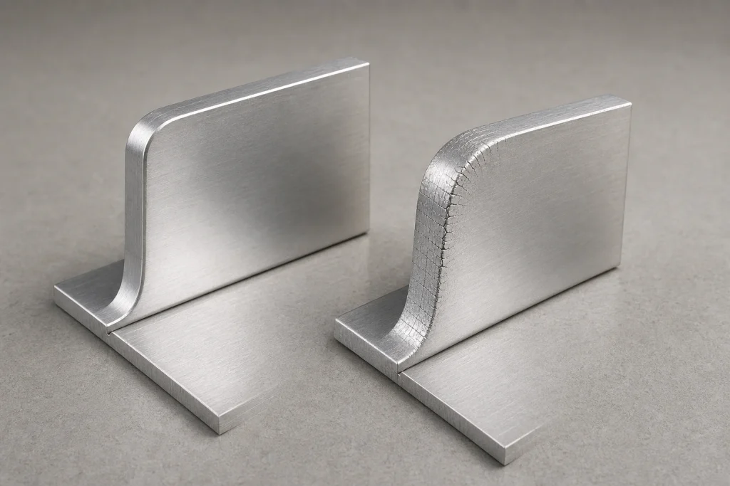
5052-H32 vs 6061-T6: The Short Answer
Choose 5052-H32 when a part needs multiple bends, tight returns, hem-like features, welded seams, or dependable corrosion resistance. Choose 6061-T6 when stiffness through geometry, higher yield strength, machined interfaces, tapped holes, or structural load capacity carry more weight than tight cold-forming performance.
The central difference in a 5052-H32 vs 6061-T6 sheet decision comes from strengthening method. 5052 belongs to the non-heat-treatable 5xxx family. Magnesium provides solid-solution strengthening, while the H32 temper combines strain hardening with stabilization. The sheet retains useful ductility for conventional brake forming.
6061 is a heat-treatable 6xxx alloy. In T6 condition, solution heat treatment and artificial aging create strengthening precipitates. That structure raises yield strength, yet leaves less plastic strain capacity for a small-radius bend. Tight tooling, a burr on the tension edge, or an unfavorable rolling direction can initiate 6061-T6 cracking before the flange reaches its final angle.
Neither alloy wins every drawing. Formed enclosures often favor 5052-H32; structural mounts may favor 6061-T6. Mixed assemblies can use folded 5052 panels and machined 6061 load-bearing members.
What H32 and T6 Mean Before the First Bend
Temper suffixes describe the condition created after alloy production. They are part of the material identity and should appear on the purchase order, drawing, and material certificate.
H32: Strain Hardened and Stabilized
The “H” identifies a strain-hardened condition. In H32, the first digit indicates strain hardening followed by stabilization, while the final “2” represents a quarter-hard degree. Stabilization moderates the property changes that can otherwise occur in magnesium-bearing alloys over time or with modest thermal exposure. The result combines useful strength with practical 5052-H32 forming behavior.
T6: Solution Treated and Artificially Aged
The “T6” condition develops strength through solution heat treatment, quenching, and artificial aging. This sequence gives 6061-T6 substantially higher yield strength than 5052-H32. It also increases springback and reduces the margin available before the outside bend fibers fracture.
Confusing alloy with temper creates expensive ambiguity. “5052 aluminum” could arrive as O, H32, or H34. “6061 sheet” could be O, T4, or T6. Substituting 6061-T6 for T4 changes the manufacturing process even though the alloy number stays the same.
5052-H32 vs 6061-T6 Bending Comparison
Published material data helps explain why the alloys behave differently. A 5052-H32 sheet data sheet from Hulamin Rolled Products lists a minimum yield strength of 160 MPa and tensile strength of 215–265 MPa across the published thickness ranges. A 2022 peer-reviewed review of 6xxx-series aluminum alloys lists 6061-T6 at 310 MPa ultimate tensile strength and 276 MPa yield strength, approximately 45 ksi and 40 ksi. Exact certified properties depend on thickness, product form, and the governing material specification, so production acceptance should use the mill test report.
| Design factor | 5052-H32 sheet | 6061-T6 sheet | Practical effect |
|---|---|---|---|
| Strengthening route | Strain hardened and stabilized | Solution treated and artificially aged | Temper controls forming response |
| Representative tensile strength | 215–265 MPa, about 31–38 ksi | About 310 MPa, 45 ksi | 6061-T6 carries higher tensile loads |
| Representative yield strength | At least 160 MPa, about 23 ksi | About 276 MPa, 40 ksi | 6061-T6 needs more forming force and springs back more |
| Cold bendability | Favorable with a validated radius | Limited at tight radii | 5052-H32 offers a wider process window |
| Welding and corrosion | Strong general performance | Good, with local strength changes after welding | Joint design and service environment still matter |
| Typical role | Covers, pans, housings, brackets | Structural mounts, machined interfaces, frames | Mixed-material assemblies can use each where it performs best |
Both alloys have a similar elastic modulus, so changing to 6061 does not dramatically increase elastic stiffness at identical geometry. It resists permanent deformation better. Increasing section depth, adding ribs, or shortening a span often improves stiffness more effectively.
How Aluminum Sheet Bending Produces Cracks
During aluminum sheet bending, the inside surface compresses while the outside surface stretches. Between them lies a neutral region with much lower longitudinal strain. Cracking begins when the local tensile strain at the outside radius exceeds what the material can tolerate in its delivered temper.
A simple screening relationship illustrates the radius effect: nominal outer-fiber strain is approximately t / (2R + t), where t is sheet thickness and R is inside radius. For a 2.0 mm sheet bent around a 2.0 mm inside radius, the estimate is about 33%. Increasing the inside radius to 6.0 mm lowers it to about 14%. Real press-brake deformation also depends on tooling contact, anisotropy, friction, and neutral-axis movement, so this equation guides comparison rather than final release.
Cracks commonly start at laser recast, punch rollover, burrs, scratches, or sharp corners. Placing the burr on the outside raises risk. Deburring matters most on harder tempers and bends near the material limit.
A 2024 peer-reviewed clinching study used 80 × 25 × 2 mm AA5052-H32 specimens and forming forces from 60 to 75 kN. At 75 kN, the stepped joint reached 5,352.4 N shear strength, 98% above the conventional joint. Although clinching differs from press-brake bending, the research demonstrates a production-relevant principle: die geometry and applied load alter local thinning and failure behavior in formed sheet.
Radius, Grain Direction, and Tooling Control the Result
The correct aluminum bend radius is a process value, rather than a decorative CAD fillet. The Aluminum Association’s design guidance identifies alloy, temper, thickness, bend orientation, and bend angle as minimum-radius variables. A drawing that gives only the final angle leaves several fracture controls undefined.
For the same alloy and temper, thicker sheet generally needs a larger absolute radius. A 180-degree return also demands more strain control than a shallow bend. Rolling direction matters because sheet develops anisotropy during rolling. The same Association guidance differentiates the two families: heat-treatable alloys are bent perpendicular to the grain, while non-heat-treatable alloys are bent parallel to it. Because drawings may use “bend direction” to mean either the bend axis or the direction of material flow, mark the rolling direction and confirm the intended orientation with the fabricator.
Tooling then converts the design into a repeatable bend. Punch nose radius, die opening, air bending versus bottoming, lubrication, surface condition, and press alignment all affect the actual inside radius. Wilson Tool’s 2023 guidance on bending aluminum likewise treats grade and temper as core tooling inputs.
Pro Tip: Put alloy, temper, thickness, inside radius, bend angle, and critical grain direction on the controlled drawing. Approve the flat pattern only after the fabricator confirms the intended tooling and bend deduction.
Why 5052-H32 Bends More Reliably and 6061-T6 Cracks
5052-H32 has a lower yield strength and a microstructure suited to cold work. Plastic deformation spreads through a larger region as the bend develops, giving the outside fibers more capacity to elongate before a crack becomes unstable. This is why formed covers, drip trays, marine housings, electrical enclosures, and multi-bend brackets frequently use 5052-H32.
6061-T6 reaches higher strength through precipitation hardening. The material resists yielding, requires higher forming force, and recovers more elastically after the punch retracts. Once a tight bend forces enough plastic strain into the outer fibers, that smaller ductility reserve can produce microcracks or a visible split. A sharp edge or bend line parallel to the rolling direction further narrows the process window.
Design teams sometimes respond by increasing tonnage. Extra force can close the tooling without restoring ductility, so it may deepen the damage. Better options include increasing the radius, selecting 6061-T4 for forming, using 5052-H32 for the folded component, or changing the geometry to a machined 6061 feature.
A crack-free bend can still miss its angle. Higher-strength 6061-T6 usually needs greater overbend compensation, verified with production-lot coupons. Correct the angle from measured free-state results rather than pressure alone.
Forming 6061 Before T6 and Using Hybrid Assemblies
If a component genuinely needs 6061-T6 strength and a demanding bend, change the process sequence. 6061-O offers the highest formability, while 6061-T4 provides an intermediate condition that often supports practical bending. The part can then undergo controlled heat treatment and artificial aging to reach the specified final temper. Heat-treatment distortion, dimensional movement, certification, and finish sequencing must enter the plan before the first prototype.
Local torch annealing may soften a bend zone, but it creates an uncontrolled property gradient and invalidates a simple T6 callout. Safety-critical or highly loaded parts need a documented thermal process, traceable material, and post-treatment verification. Welding creates a related issue because the heat-affected zone no longer retains the original T6 properties without subsequent treatment.
Another route divides the functions. Fold 5052-H32 into the enclosure, guard, duct, or cable shield. Use 6061-T6 for a bolted rail, bearing seat, optical datum, threaded block, or thick structural mount. The aluminum CNC machining service from BOONA can support the rigid element while sheet fabrication provides the lightweight skin.
Hybrid design adds fasteners and tolerance interfaces, yet often removes bend risk and simplifies finish control.
Choose the Alloy by Part Function
Start with the dominant failure mode. Use 5052-H32 when bend cracking, corrosion exposure, weldability, or multi-flange forming controls the design. Use 6061-T6 when permanent set at a bolted joint, thread strength, bearing support, or a precisely machined datum drives acceptance. If both lists matter, separate the sheet and structural functions.
Mini Case: A Field-Weeding Vision Assembly
A 2024 Agronomy study evaluated a field-weeding robot with a 2 m aluminum camera boom, 20 mm outside diameter, 2 mm wall thickness, and a maximum travel speed of 0.7 km/h. The camera operated 2 m above the crop, and one recording session stopped because of rain. Those details create a real design problem: the vision hardware needs weather protection while the camera position must remain stable under field motion.
The paper does not identify a 5052 or 6061 temper for a camera housing, so the following material split is an engineering inference. A folded 5052-H32 rain hood can carry drain features, returns, and sealed seams without forcing tight bends into T6 sheet. A compact 6061-T6 machined clamp can control the camera datum and resist bolt preload. Here, weather interruption and image-position stability drive different components toward different manufacturing routes. The assembly gains formability at the protective skin and localized strength at the mount without asking one alloy to satisfy incompatible forming demands.
Inspection and RFQ Details That Prevent Production Surprises
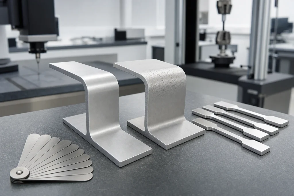
Inspection should address the bend as a formed feature. Check the free-state angle, inside radius, flange length, profile, hole position after forming, and surface condition along the outside radius. Magnified visual inspection can reveal edge microcracks before coating hides them. For critical parts, the quality plan may add liquid penetrant inspection, sectioned qualification coupons, or destructive bend testing at an agreed sampling rate.
An actionable RFQ should include:
- Alloy and full temper, such as 5052-H32 or 6061-T6
- Certified thickness range and any mill-certificate requirement
- Finished 3D model plus a controlled 2D drawing
- Inside bend radius, bend angle, and applicable tolerances
- Rolling direction for critical bends, if controlled
- Cosmetic face, deburring standard, and allowed edge condition
- Welds, inserts, hardware, coating, masking, and post-treatment requirements
- Prototype and production quantities, plus the inspection report required
Avoid solving springback by tightening every dimension. Define functional datums and critical interfaces, then allow realistic variation on nonfunctional flanges. If a small radius is mandatory, qualify a production-lot bend coupon before releasing the full quantity. It can verify cracks, final angle, surface marking, and bend deduction.
Clear revision control matters too. A change from H32 to H34 or T4 to T6 alters the forming window and should trigger a manufacturing review, even when the alloy number and CAD geometry remain unchanged.
FAQs
Is 5052-H32 Stronger Than 6061-T6?
No. 6061-T6 generally has higher tensile and yield strength. 5052-H32 usually offers better cold-forming behavior and corrosion resistance. Let geometry and load case set the priority.
Can 6061-T6 Sheet Be Bent to 90 Degrees?
Yes, if thickness, radius, rolling direction, edge quality, and tooling provide enough strain margin. Tight bends carry more cracking risk than comparable 5052-H32 bends. Qualify critical features with the production lot.
What Bend Radius Should I Use for 5052-H32 Aluminum?
There is no universal value. Radius depends on thickness, angle, rolling direction, material specification, and tooling. Start with mill guidance and fabricator feedback, then document the qualified value.
Why Does 6061-T6 Crack Along the Outside of a Bend?
The outside fibers experience tension. T6 hardening reduces the plastic strain margin for a tight bend. Burrs, scratches, small radii, and unfavorable grain orientation can then initiate a crack.
Can 6061 Be Bent First and Heat Treated to T6 Afterward?
Yes. Forming in O or T4 and applying controlled heat treatment can deliver a T6 final condition. Account for distortion, reinspection, certification, coatings, and inserted hardware.
Should an Enclosure Use 5052 While Its Mounts Use 6061?
Often, yes. Folded 5052-H32 panels handle flanges, seams, and weather protection efficiently. Machined or thicker 6061-T6 mounts provide stronger threads and accurate load-bearing interfaces. Joint design, corrosion compatibility, and tolerance stack-up still require review.
Conclusion: Make the Bend Part of Material Selection
The practical lesson from 5052-H32 vs 6061-T6 is straightforward: specify the forming behavior alongside the final mechanical requirement. 5052-H32 usually gives designers more freedom for tight radii, multiple bends, and welded sheet assemblies. 6061-T6 supplies higher yield strength for structural mounts and machined interfaces, while demanding more conservative bend geometry or a different temper sequence.
Successful drawings connect material, temper, thickness, inside radius, bend direction, edge quality, tooling assumptions, finish, and inspection. A prototype bend coupon then confirms the process before production volume amplifies a small crack into a schedule problem.
If your part combines tight bends, structural interfaces, welding, or post-finish dimensional requirements, send BOONA the 3D model and controlled drawing. Through its sheet metal fabrication service, BOONA can review alloy and temper, bend radii, grain direction, tooling access, and inspection requirements. There is no minimum order quantity, and every quote includes a complimentary DFM review. Send your CAD for a technical review.


