
An implant concept can look convincing on a screen and still fail a physical design review. Its outer contour may not follow the reconstructed anatomy closely enough. A planned screw path may conflict with surrounding geometry. An instrument may not have enough access during placement. A thin edge may also distort during manufacturing or break during repeated handling.
Medical implant prototyping gives medical-device teams a practical way to find these problems before the design enters a regulated implant-production process. Engineers can use 3D printed anatomical models, non-implantable fit-check samples, CNC-machined development parts, inspection fixtures, and test coupons to evaluate geometry without treating an early prototype as a clinically usable device.
The stakes justify careful development. A 2025 systematic review of patient-specific maxillofacial implants included eight studies and 183 patients. Six studies contributed to a meta-analysis that reported a pooled implant success rate of 94.7%, with a 95% confidence interval of 91.4% to 98.0%. The authors also noted that the available studies were mainly observational, so the results should not be applied broadly to every implant type or patient group. Review the study in PubMed.
This article focuses on development models, engineering prototypes, fixtures, and validation components. Final implant manufacturing requires application-specific materials, qualified processes, regulatory controls, and documented release responsibility.
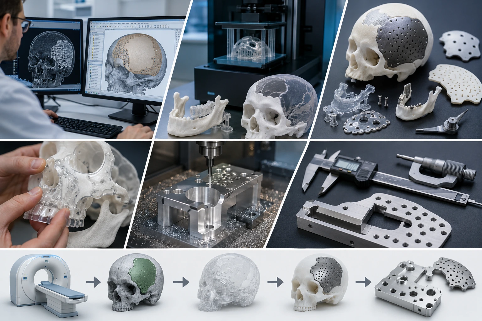
What Medical Implant Prototyping Actually Covers
Medical implant prototyping describes the physical validation work completed before final regulated production. It may involve a representation of the patient’s anatomy, a non-implantable copy of the proposed implant, a surgical access model, a mechanical test part, or a fixture used to inspect the design.
These parts answer different questions:
| Development Part | Main Purpose | Intended for Implantation? |
|---|---|---|
| Anatomical model | Review bone geometry, defects, and access | No |
| Implant fit-check model | Evaluate contour, coverage, and placement | No |
| Functional development prototype | Test assembly, handling, or mechanical concepts | Usually no |
| Surgical instrument concept | Evaluate access, grip, and alignment | No |
| Inspection fixture | Check repeatable dimensions or positioning | No |
| Final regulated implant | Perform the intended clinical function | Yes |
The distinction prevents a common sourcing mistake. A resin skull model and a titanium implant may originate from related CAD geometry, but they do not share the same manufacturing, biological, documentation, or release requirements.
Boona guide to medical 3D printing for anatomical models and prototypes explains how CT, MRI, and CAD data can become physical models for planning and product development. Implant-focused prototyping narrows that workflow toward fit, fixation, access, inspection, and manufacturability questions.
Where Prototypes Fit in Patient-Specific Implant Development
A patient-specific development project often begins with CT data, although the clinical team determines the appropriate imaging method. Segmentation software separates the target anatomy from the surrounding scan data and converts it into a usable three-dimensional model.
Engineers then create or evaluate the implant concept against that reconstructed anatomy. Before physical production, the team should define what the prototype must prove. A model for visual review has different requirements from a sample used to check a screw trajectory or precision mating surface.
A practical development sequence may include:
- Freeze the approved imaging dataset.
- Segment and reconstruct the relevant anatomy.
- Create the preliminary implant geometry.
- Review the contour, fixation plan, and surgical access digitally.
- Produce an anatomical model and non-implantable fit-check sample.
- Record physical fit observations and design changes.
- Manufacture fixtures, gauges, or functional engineering samples.
- Complete DFM review before transferring the design into its regulated production pathway.
The FDA’s additive-manufacturing guidance addresses far more than printing. It identifies technical considerations involving design, software workflow, material controls, build orientation, process validation, post-processing, cleaning, and device testing. Read the FDA technical guidance.
Prototype work should support this controlled process rather than bypass it.
How 3D Printing Supports Medical Implant Prototyping
3D printing works especially well when the development part contains complex anatomical contours that would require excessive setup time or material removal through conventional machining. A skull section, pelvic defect, mandibular model, or irregular bone-contact surface can often be printed directly from repaired digital geometry.
Different printing technologies answer different development questions. SLA can provide smooth surfaces and fine visible detail for anatomical models. SLS and MJF nylon parts withstand more repeated handling and may suit functional fit checks, snap features, or instrument-clearance studies. FDM can produce larger early-stage models at a lower cost when fine surface detail is not the main goal.
Boona custom 3D printing services can support non-implantable anatomical models, medical-product concepts, handling samples, development fixtures, and fit-check components. The process should follow the prototype’s intended use rather than the popularity of a specific printing method.
For example, a cranial contour model may need a smooth external surface and clearly defined defect boundary. A reusable assembly fixture may need stronger PA12 nylon. A transparent vascular model may prioritize visibility over impact strength.
The printed model does not need to reproduce every scan artifact. It needs to preserve the landmarks, boundaries, access areas, and interfaces that affect the engineering decision.
When CNC Machining Adds More Value
Additive manufacturing offers geometric freedom, but CNC machining often provides better control over precision holes, flat datum surfaces, threads, slots, and mechanically loaded development parts.
A medical-device team may first print the anatomical geometry, then CNC machine a separate interface plate, test fixture, instrument concept, or final-material engineering sample. Combining both methods allows the printed model to represent complex anatomy while the machined component provides accurate assembly features.
CNC machining is particularly useful for:
- Screw and dowel-hole patterns
- Flat implant-interface test surfaces
- Threaded instrument components
- Inspection gauges and nests
- Metal handling prototypes
- PEEK, aluminum, stainless steel, or titanium development parts
- Mechanical samples for load or assembly testing
For selected functional features, a team might specify ±0.02 mm to ±0.05 mm tolerances while allowing broader tolerances on noncritical profiles. The actual requirement depends on part size, material, geometry, inspection method, and what the test needs to prove.
Boona precision CNC machining services support metal and engineering-plastic prototypes where dimensional control and material behavior matter more than anatomical complexity.
CNC machining should not be added simply to make a prototype look more advanced. It earns its place when a hole, mating surface, thread, datum, or material property affects the development decision.
Choosing the Right Prototype Process and Material
A prototype material should match the test rather than imitate the final implant only in appearance. Early visual models, functional handling samples, precision fixtures, and final-material engineering parts all have different requirements.
| Process or Material | Best Development Use | Key Limitation |
|---|---|---|
| SLA rigid resin | Detailed anatomical models and visual fit checks | Can be brittle under repeated mechanical use |
| Clear resin | Viewing internal pathways and overlapping geometry | Requires careful finishing for optical clarity |
| SLS or MJF PA12 | Durable handling models and functional fixtures | Raw surface has a slightly granular texture |
| FDM thermoplastic | Large concept models and early spatial checks | Visible layers and lower fine-feature resolution |
| CNC aluminum | Fixtures, instruments, plates, and rigid test parts | Does not reproduce complex anatomy efficiently |
| CNC PEEK | High-performance plastic development components | Material cost and machining control are higher |
| CNC stainless steel | Wear-resistant tools, pins, and test components | Heavier and slower to machine |
| Machined titanium | Metal design validation and process studies | Higher material and machining cost |
Prototype-grade resin should not be described as implantable merely because a similar-looking polymer has a medical application. The same caution applies to PEEK and titanium. Material grade, traceability, processing history, contamination control, and final validation determine whether a finished device can enter a clinical pathway.
During early development, teams may use a lower-cost material to confirm geometry, then move to a more representative material for mechanical, thermal, or dimensional testing. Each prototype should have a written purpose so the team knows which conclusions it can support.
DFM Problems to Find Before Regulated Production
Medical implant development becomes more expensive when basic geometry problems survive too far into the project. A physical prototype can expose issues that remain difficult to judge in a rotating CAD model.
Common DFM risks include an edge that becomes too thin after contour adjustment, a screw hole positioned too close to a boundary, or a closed cavity that complicates powder removal. Deep channels may trap support material. Sharp internal corners can create machining or stress problems. A surgeon may also discover that the planned tool angle looks reasonable digitally but offers limited physical access.
Data and version control deserve the same attention as geometry. Teams should identify:
- The approved imaging dataset
- The segmentation revision
- The implant-concept revision
- The file used for each physical prototype
- The reviewer and approval date
- The dimensions treated as critical
- The inspection method for those dimensions
A prototype supplier can identify manufacturing risks, but the medical-device team must define clinical intent and regulatory responsibility. Boona article on DFM analysis in medical-device prototyping explains how early process review can reduce avoidable redesign and clarify which features need tighter control.
💡 Pro Tip: Include the anatomical model, implant concept, and critical dimensions in the same design review. Reviewing them as separate files makes it easier to miss a contact, clearance, or access conflict between them.
Application Example: Cranial Implant Fit-Check Development
Consider a medical-device team evaluating a patient-specific cranial reconstruction concept. The clinical team supplies an approved CT-derived skull model with a defined defect boundary. Engineers reconstruct the missing contour and create an early implant concept, but they do not send that first design directly into final regulated production.
The team prints a rigid anatomical model of the affected skull region and a separate non-implantable implant-shaped sample. During the physical review, the sample reveals uneven contact along one edge of the defect. A planned screw position also sits too close to a thin anatomical boundary, while an instrument has less access than expected from the digital view.
Engineers revise the contour, move the screw position, and produce another fit-check sample. They define a physical edge-gap target of less than 0.5 mm for the development review and mark the screw-center positions as critical inspection features. A CNC-machined drilling or inspection template then verifies the revised hole pattern against the model.
The process does not prove clinical safety or authorize implantation. It proves that the design team has addressed several geometric questions before the project moves into more expensive validation and regulated manufacturing.
This type of staged review is more useful than ordering a polished prototype with no written acceptance criteria. Each physical part should answer a specific question and produce a documented decision.
Quality, Data Security, and Supplier Responsibilities
Medical development files may contain patient-derived geometry, proprietary device concepts, or both. Before transferring data, the customer and supplier should agree on file handling, access, storage, retention, and deletion expectations.
The RFQ should also state the development status clearly. Terms such as “anatomical model,” “non-implantable fit-check prototype,” “engineering sample,” and “inspection fixture” reduce the risk of misunderstanding. The supplier should not assume that a part is suitable for clinical use because the CAD resembles an implant.
A useful prototype package includes:
- A STEP or STL file with a controlled revision
- A 2D drawing for critical dimensions
- The prototype’s intended development use
- Material and process requirements
- Surface-finish expectations
- Inspection points and reporting needs
- Quantity and revision status
- A statement confirming whether the part is non-implantable
The supplier should also explain which processes remain in-house, which operations require an approved partner, and how revisions are controlled.
For early concepts, Boona rapid prototyping support can combine physical-model production with iterative engineering review. The medical-device company still retains responsibility for intended use, regulatory strategy, clinical approval, and final device release.
FAQs About Medical Implant Prototyping
What is a medical implant prototype?
A medical implant prototype is a development part used to evaluate geometry, fit, handling, assembly, access, or manufacturability. Unless produced and released through the applicable regulated process, it should not be treated as a clinically usable implant.
Can a prototype implant be used in surgery?
A general development prototype should not be used as an implant. Final clinical use requires the appropriate material controls, validated manufacturing, testing, regulatory pathway, sterilization, labeling, and release procedures.
How are anatomical models made from CT scans?
A qualified team segments the required anatomy from DICOM imaging data, reconstructs the geometry, repairs the digital model, and prepares it for an appropriate printing process. The model’s intended purpose determines the required detail and accuracy.
Which material is best for an implant fit-check model?
Rigid SLA resin can work well for detailed visual fit checks. PA12 nylon may suit models that require repeated handling. CNC-machined plastic or metal may be better when the team needs accurate holes, flatness, threads, or representative material behavior.
When should CNC machining replace 3D printing?
CNC machining becomes useful when the prototype requires tight dimensions, precision interfaces, machined threads, metal strength, or final-material testing. It often complements rather than completely replaces 3D printing.
What information should be included in an RFQ?
Include controlled CAD files, a 2D drawing for critical dimensions, intended prototype use, material, finish, quantity, inspection requirements, and a clear statement on whether the part is a non-implantable development component.
Medical Implant Prototyping Reduces Uncertainty Before Production
Medical implant prototyping helps product teams evaluate anatomy, contour, fixation concepts, surgical access, inspection methods, and manufacturability before a design enters regulated production.
3D printing provides a practical route for complex anatomical models and rapid fit checks. CNC machining supports accurate holes, flat surfaces, threads, fixtures, and representative engineering materials. Used together, the two processes can reveal design risks that remain difficult to assess through digital review alone.
A prototype should never carry more meaning than its test supports. A visual model proves appearance and spatial understanding. A fit-check sample evaluates geometry. A CNC fixture checks location or repeatability. None of these steps alone proves that a final implant is clinically safe or approved.
The strongest development workflow defines the question first, selects the process second, and documents the result before moving forward.
Validate Your Medical Implant Concept Before Regulated Production
Boona supports anatomical models, non-implantable fit-check samples, medical-device prototypes, inspection fixtures, and precision development parts using 3D printing and CNC machining. Send your controlled CAD files, drawings, intended prototype use, and critical requirements through Boona custom 3D printing service for a manufacturability review and prototype quotation.


