
During a planned machine changeover, a technician must remove a guide sleeve while leaving its housing in place. The replacement needs accurate location, yet any permitted interference complicates removal. That maintenance requirement should influence the fit before the drawing reaches purchasing.
For H7/g6 vs H7/k6 vs H7/p6, the starting distinction is clearance, transition, and commonly interference, respectively. Choose H7/g6 where controlled movement or removal matters. Consider H7/k6 for close location when assembly can accommodate either clearance or interference. Evaluate H7/p6 for retention, then calculate its limits at the actual nominal diameter.
The complete decision also includes materials, surface condition, and operating temperature. A fit designation describes permitted sizes; it does not establish press force, torque capacity, or assembly reliability.
H7/g6 vs H7/k6 vs H7/p6 at a Glance
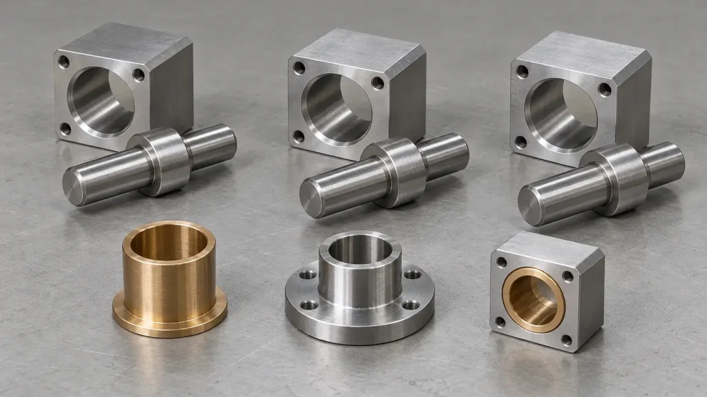
These combinations hold the hole designation at H7 and change the shaft tolerance zone. The resulting fit determines what assembly and maintenance must accommodate.
| Selection factor | H7/g6 | H7/k6 | H7/p6 |
|---|---|---|---|
| Typical fit category | Clearance | Transition | Commonly interference; verify diameter |
| Functional priority | Movement or removal | Close location | Frictional retention |
| Assembly consideration | Alignment and available clearance | Possible clearance or interference | Pressing or controlled thermal assembly |
| Maintenance implication | Generally easier to remove | Actual fit affects removal | Removal needs deliberate planning |
| Main engineering concern | Play and minimum operating clearance | Variable assembly behavior | Retention, hub stress, and deformation |
Use this as a selection framework rather than a universal application chart. A removable sleeve still needs an allowable-play requirement. A locating hub may require separate axial retention. A retained bushing needs an assessment of the surrounding housing.
Interchangeability deserves attention early. A precisely specified bore cannot deliver a predictable fit if its replacement shaft carries unspecified limits.
Keep load-bearing function separate from fit category. Even a clearance-fit shaft may transmit torque through a key, while an interference-fit joint depends on contact pressure and friction unless another retention feature carries the load.
How to Read H7, g6, k6, and p6
The Hole-Basis System
Uppercase letters identify hole zones; lowercase letters identify shaft zones. An H hole has zero lower size deviation, placing the start of its permitted size interval at nominal size.
The numbers specify tolerance grades. Their widths change with nominal-size interval. H7 therefore does not mean a fixed numerical allowance or a symmetric plus/minus tolerance.
ISO 286-1:2010 defines the system’s terminology and hole-basis principles. ISO 286-2:2010 provides the tabulated limit deviations. Their catalog entries list both editions as current following confirmation in 2026 and identify published 2013 corrigenda.
Position and Width Do Different Jobs
The letter positions a tolerance zone relative to nominal size. The grade determines its width.
For the same diameter interval, g6, k6, and p6 share the same grade width. Switching between them changes the permitted shaft size rather than automatically making its tolerance narrower.
Transition behavior comes from overlap between the hole and shaft intervals. The k6 shaft zone does not need to straddle nominal size to create a transition fit.
Read the actual component limits together. The letter alone cannot describe the dimensional relationship of a finished pair.
H7/g6 vs H7/k6 vs H7/p6: A Worked Diameter Example
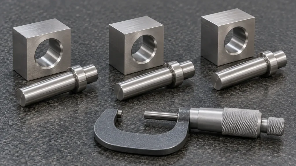
Establish the Component Limits
Use an illustrative nominal diameter of 30 mm. Tables 2.3 and 2.4 in the Engineering College of Technology’s mechanical engineering teaching manual supply the grade widths and fundamental deviations used below. The relevant rows cover sizes over 18 through 30 mm for the grade widths and over 24 through 30 mm for the shaft deviations.
Combining those published values with the selected diameter gives:
| Feature | Minimum size, mm | Maximum size, mm |
|---|---|---|
| H7 hole | 30.000 | 30.021 |
| g6 shaft | 29.980 | 29.993 |
| k6 shaft | 30.002 | 30.015 |
| p6 shaft | 30.022 | 30.035 |
Calculate the Worst-Case Fit
Use signed diametrical clearance:
Minimum clearance = minimum hole size − maximum shaft size
Maximum clearance = maximum hole size − minimum shaft size
The calculated results are:
- H7/g6: 7–41 μm clearance.
- H7/k6: 15 μm interference through 19 μm clearance.
- H7/p6: 1–35 μm interference.
Positive signed clearance means a gap; negative signed clearance means interference. A zero endpoint permits a line-to-line boundary condition.
Evaluate both extremes. Maximum clearance governs the possible looseness of a locating interface. Minimum interference governs frictional-retention calculations, while maximum interference drives assembly and stress checks. The small lower bound in the p6 example makes the finishing allowance and measurement decision rule relevant RFQ questions.
Do not carry these values into another diameter interval. Small-diameter H7/p6 combinations can permit interval overlap or a line-to-line endpoint. Also check whether an assembly calculation uses radial or diametrical interference; confusing them changes the input substantially.
Choose by Function: Movement, Location, or Retention
Clearance for Movement and Removal
H7/g6 is a candidate for removable sleeves and guided components where a controlled gap suits the mechanism. Define permissible play and evaluate the smallest clearance under operating conditions.
A removable part still needs alignment during insertion. If the interface moves continuously, evaluate lubrication and contact materials alongside its dimensional fit.
Transition for Close Location
H7/k6 suits interfaces where close location matters and assembly can accommodate either clearance or interference. The permitted size combination determines the outcome.
If axial movement or rotation is unacceptable, plan suitable retention. Selective assembly may reduce variation, but it also changes replacement-part interchangeability and should appear explicitly in the procurement requirements.
Interference for Retention
H7/p6 deserves consideration when frictional retention suits the joint. Check engagement length, wall thickness, and material strength before choosing the assembly method.
A press-fitted bushing may change its internal bore after installation. Distinguish its supplied dimensions from the installed functional requirement.
Bearing seats require application-specific guidance on loading, ring behavior, and internal clearance. The comparison here concerns general shaft-and-hole interfaces.
Application Example: Railway Wheel-Seat Fatigue
A railway-axle study published online in 2025 examined how press-fit loading contributes to fatigue assessment. Section 2.1.2 modeled interference from 0.2 to 0.3 mm, centered on 0.25 mm. Section 2.4 describes validation using three full-scale EA4T axles with artificial crack starters at the T-notch.
The researchers combined wheel-seat press-fit loading with cyclic bending and manufacturing residual stresses. This concerns fatigue-crack propagation in railway axles, rather than a comparison of the three fit combinations.
It was independent research, not a BOONA project or evidence of BOONA capability. The engineering inference is to evaluate retention and fatigue separately, particularly near contact boundaries where the surrounding geometry affects stress.
Why Diameter Limits Alone Cannot Guarantee Function
Form, Alignment, and Surface Texture
Local size measurements can miss taper or form errors that affect assembly over the engagement length. Specify relevant geometric controls and datum relationships. Define an envelope requirement where the intended function needs it.
Surface texture also affects contact. Asperities may flatten during pressing, changing the effective interface. A diameter limit does not describe those surface interactions.
Temperature and Material Combinations
An aluminum housing and steel shaft can change their fit as temperature changes. Unequal component temperatures can matter during assembly and operation.
Evaluate the relevant temperature conditions and material expansion together. Inspection at the agreed reference condition confirms dimensional acceptance; it does not establish the operating clearance throughout service.
Coatings and Finishing Allowances
Deposited coatings can enlarge a shaft and reduce a bore. Anodic oxide grows through conversion of the aluminum surface, so total coating thickness and dimensional growth require separate consideration.
A 2023 steel–brass nickel-plating experiment demonstrates another finishing effect. Section 3 and Figure 6 report a 10–20% increase in measured axial load capacity at a mean interference of 12 μm. The same section’s discussion of Table 2 reports approximately 20% difference in calculated friction coefficients after three joining and disassembly cycles.
These findings apply to the tested material pair and preparation route. This was not a BOONA project and does not demonstrate BOONA capability. The engineering inference is to qualify the finished contact pair rather than assume that equal interference produces equal retention.
Pro Tip: For an interference joint, document the minimum interference used for retention calculations and the maximum used for assembly and stress checks. A nominal value leaves both questions unresolved.
Manufacturing, Inspection, and Fixture Cost
Select the Process Around the Feature
Precision boring or reaming may suit a hole; turning or grinding may suit a shaft. Access and material condition influence the route, as do geometric requirements.
For BOONA fit-part RFQs, our DFM recommendation is to identify the functional bore land separately from the lead-in and any relieved section. Carrying a tight bore requirement unnecessarily into a blind shoulder can restrict tool travel and complicate gauging. A relief needs sufficient definition to preserve the required support and engagement.
Discuss these features through BOONA’s CNC turning services for shafts and cylindrical components.
Plan Gauging Alongside Finishing
Our inspection-planning recommendation is to resolve gauge access before finalizing the bore-finishing sequence. A gauge entering only the chamfer cannot establish the size of the full mating land. Define where measurements must occur and what form checks support the acceptance decision. Agree when final sizing occurs relative to finishing and what inspection evidence covers the full land.
A thin-walled component may also change shape after release from its fixture. Specify the acceptance condition rather than relying on the clamped geometry.
Changing g6 to p6 mainly relocates the shaft tolerance zone. Tool access, finishing allowance, and inspection effort can create larger cost differences than the fit letters themselves.
Drawing and RFQ Checklist
Show the combined fit on assembly documentation where appropriate, then specify the individual bore and shaft requirements on their component drawings. Resolve discrepancies before purchasing releases either part.
A fit-specific RFQ should include:
- Nominal diameter and functional engagement length.
- Individual hole and shaft tolerance classes.
- Material grades and material condition.
- Finished dimensional limits and coating coverage.
- Masking boundaries and permitted processing-contact locations.
- Relevant geometric controls and datum relationships.
- Surface texture on the mating lands.
- Lead-in geometry and permissible edge breaks.
- Assembly method, retention function, and removal access.
- Inspection method and delivered acceptance condition.
Include the controlled drawing of a mating part purchased elsewhere. A nominal CAD model cannot supply missing shaft or bore limits.
For bushings, clarify whether acceptance applies before installation or to the installed bore. BOONA’s component inspection does not establish the complete assembly’s holding force or fatigue life.
Keep replacement expectations explicit. A part intended to fit any conforming mating component has different purchasing implications from a selectively paired set.
FAQs
What is the difference between H7/g6, H7/k6, and H7/p6?
They use the same hole designation with different shaft tolerance zones. H7/g6 provides clearance, H7/k6 typically provides transition behavior, and H7/p6 commonly provides interference. Verify the numerical limits at the actual nominal diameter.
Does H7 always mean the same numerical tolerance?
No. Its grade width depends on the nominal-size interval. H defines the hole-zone position, while the grade identifies its width. The drawing needs the nominal size as well as the tolerance class.
Can H7/k6 have clearance?
Yes. Its permitted hole and shaft sizes can produce clearance or interference. Plan assembly for both possibilities unless the specification deliberately introduces selective pairing or a different acceptance arrangement.
Is H7/p6 always an interference fit?
Check the applicable size row. Small-diameter combinations can permit interval overlap or a line-to-line endpoint. Even where interference is guaranteed dimensionally, holding force depends on additional joint parameters.
How do plating and anodizing affect fits?
They change finished dimensions and can change contact behavior. Specify final acceptance limits, coating coverage, and any masking or final sizing process. A universal coating allowance cannot describe every finishing route.
Can CNC machining achieve H7 without reaming?
A suitable boring or other finishing process may achieve the specified limits. Reaming is one option. Geometry, access, material, and the inspection plan determine which route is appropriate.
Conclusion: Choose the Fit Around the Finished Joint
The H7/g6 vs H7/k6 vs H7/p6 decision should follow the required interface behavior. Begin with movement or removal, close location, or frictional retention. Calculate the permitted sizes at the selected diameter, then evaluate the unfavorable end of the range for each function.
The resulting drawing should describe the finished mating surfaces and the acceptance condition. Keep the supplied component requirements distinct from the installed assembly’s performance requirements. That distinction matters when the mating part comes from another supplier or when coating follows machining.
Send BOONA the mating drawings, material grades, and finishing requirements for a free DFM review. With no minimum order quantity, our custom CNC machining service supports prototype and production-part enquiries. Include both component limits so the review addresses the actual fit.


