
A charging cable pulled across a parking bay applies a different load to its supporting hardware than the same cable hanging beside the charger. Specifying only charger weight leaves that load path undefined, along with connector-storage orientation and fastener access.
Machining EV charger pedestals, brackets and holsters starts with those interfaces. The practical route often combines a fabricated pedestal structure with selectively machined mounting features. Brackets need controlled location and suitable fastening; holsters require connector-specific clearance and retention geometry.
Define the installed configuration before choosing materials or tightening tolerances. BOONA supplies components to the agreed specification; complete-charger qualification and site approval require separate validation.
Machining EV Charger Pedestals: Choose the Right Process
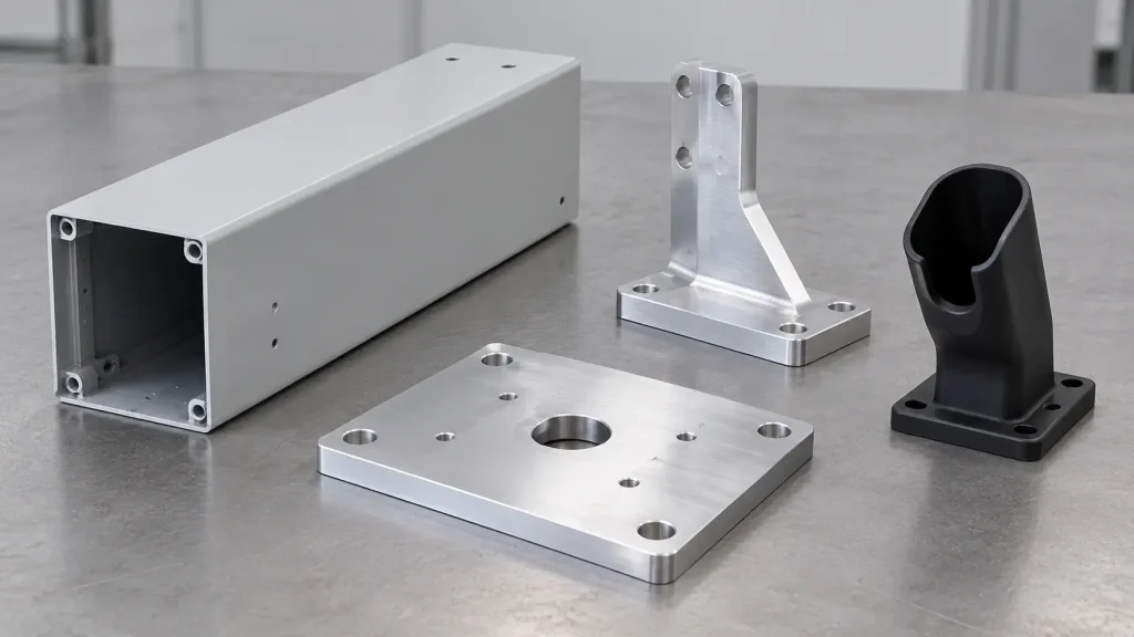
Pedestals: Fabricate the Structure, Machine Selected Interfaces
A tall pedestal rarely needs to start as a solid billet. Formed sheet, welded sections or an extrusion may provide the main structure, with machining reserved for features whose location or surface condition affects assembly.
Compare the complete route, including fixturing, joining and finishing. An accessible adapter plate can sometimes provide the required precision without finish-machining a large weldment.
| Component | Manufacturing routes to evaluate | Where machining adds value |
|---|---|---|
| Pedestal body | Formed sheet, welded sections or extrusion | Selected mounting pads and attachment features |
| Base plate | Cut plate with secondary machining | Specified locating features and fastener seats |
| Charger bracket | Bent sheet, extrusion or machined stock | Controlled offsets, interfaces and insert seats |
| Connector holster | Machining, polymer casting or injection molding | Connector-specific geometry and prototype changes |
Brackets and Holsters: Let Function and Volume Guide the Process
Bent brackets can reduce material removal, while machined brackets accommodate substantial offsets and accurately related faces. Evaluate both against loads and service access.
For holsters, machining supports geometry changes without dedicated molding tooling. Polymer casting may support development batches, but a cast replica does not automatically reproduce the behavior of the intended production thermoplastic.
BOONA sheet-metal fabrication services provide a relevant route for formed panels and brackets alongside separately machined interfaces.
Select Materials for the Component and Exposure
Metal Structures and Mounting Components
Specify the material’s grade, condition and product form. A design intended for bending presents different requirements from a mounting block machined from plate.
For aluminum, suitable 5xxx-series sheet can serve formed panels, while 6061 plate or extrusion may suit machined mounting components. Confirm the grade and temper against the actual bending, joining and finishing requirements.
Coated carbon steel may suit structural parts; stainless steel can be relevant where exposure and maintenance justify it. Each route still requires attention to crevices, drainage and dissimilar-metal contact.
Include the actual environment in the RFQ. A sheltered parking structure and a coastal roadside installation should not receive identical assumptions about corrosion or cleaning.
Polymer Holsters and Replaceable Contact Parts
Select an exact polymer grade rather than relying on a family name. Candidate materials might include POM, nylon or weatherable engineering-plastic grades, subject to the application.
Check creep under sustained cable loading, impact behavior and wear at retention features. Outdoor use also requires grade-specific evidence for weathering and temperature exposure.
If the design requires particular fire or electrical properties, identify the applicable material and finished-equipment requirements. A machinable polymer’s generic datasheet does not establish suitability for every charging application. Make frequently worn contact pieces accessible for replacement.
Control Pedestal and Bracket Interfaces Through Manufacturing
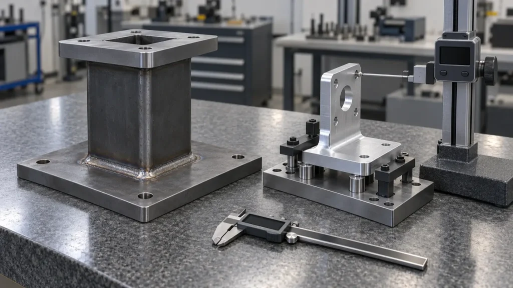
Define the Complete Mounting Stack
Trace the charger, adapter, bracket, pedestal and base plate through to the installation interface. Clearance slots allow adjustment; they should not silently become precision locating features.
Loads depend on configuration. In the 2026 ChargeX connector-load report, Section 4.4.1, Table 9, row 11 reports an approximated X-axis force of 137 N and lateral rotational torque of 57 N·m for one NACS–CCS configuration with its cable stretched to C1. However, rows 7–9 show lower X-axis forces for the CCS–NACS adapter cases; the accompanying discussion attributes this to loose mechanical fit allowing the cable to relax. Section 4.5 explains how added adapter length can increase torque through a longer lever arm.
Section 5 recommends raising the misalignment test force from 100 N to 125 N. This is a research recommendation, not evidence of an adopted requirement. These connector–inlet measurements concern DC fast-charging tests; they are not prescribed pedestal or holster loads. The independent report is not a BOONA project and does not demonstrate BOONA capability. The engineering inference is to evaluate actual cable routing, interface fit and lever arms together.
Sequence Fabrication and Critical Machining
For a BOONA DFM review, our recommendation is to identify the weld-completed condition before quoting final mounting-pad machining. Welding after finishing a critical interface may create a need for rework.
Where post-weld machining is required, provide access, suitable support and feasible machining allowance. If an adjustable adapter plate can isolate the precision interface, compare that route before specifying tight location requirements across the whole weldment.
Choose Fastening Features That Suit the Material
Evaluate tapped holes, inserts, captive nuts, studs and through-bolts against material thickness and tool access. Check the wrench envelope with the charger installed. A fastener accessible during bench assembly may become trapped once the equipment covers the bracket.
The responsible designer must establish structural and anchorage requirements. An equipment pedestal is not automatically a vehicle-impact protection bollard.
Design Holsters Around the Actual Connector and Cable
Separate Storage Geometry From Electrical Connection
A storage holster supports and retains a connector when parked. It is distinct from an energized connector or vehicle inlet.
Our BOONA RFQ recommendation is to identify the physical connector revision before freezing the holster cavity. A connector-family label may leave differences in handle shape, latch travel or cable-exit hardware unresolved. Supply an approved sample or controlled mating model.
Evaluate Retention, Release and Cable Routing Together
Check insertion angle, release access and the removal envelope with the cable attached. Provide appropriate drainage and avoid recesses that collect debris.
The “Connectors” and “Charging Cables” sections of the U.S. Access Board’s charging-station guidance address handling and cable-management considerations. Distinguish its recommendations from applicable requirements; component geometry alone cannot establish site accessibility.
Pro Tip: Approve the holster with the actual connector hanging from its cable in the intended mounting orientation. An unsupported connector sample leaves cable-induced rotation and release access unevaluated.
Field Example: Charging Hardware That Could Not Reach the Vehicle
A Human Factors field study first published in 2023 provides a practical packaging example. Table 2, “Functional States of 655 CCS DCFC EVSEs,” records 21 ports, or 3.2%, under “Cable would not reach.” The opening paragraph of “Results” dates the field visits to 2022 and identifies the San Francisco Bay Area study setting. The subsection “Reliability of EVSEs” identifies Chevrolet Bolts in the short-cable cases.
This independent study was not a BOONA project and does not establish BOONA capability. It measured station usability, rather than machined-part accuracy.
The engineering inference is to validate pedestal placement, cable routing and connector handling together before releasing mounting geometry. A dimensionally correct bracket cannot compensate for an unsuitable installed reach envelope.
Coordinate Coatings, Fit and Bonding Features
Specify the Finish Beyond Its Color
A color designation does not define a complete outdoor coating system. State the substrate preparation, coating requirements and intended exposure. Identify cosmetic acceptance separately from functional fit.
Clarify whether each critical dimension applies before or after finishing. Coating buildup can affect clearance holes, threaded features and the seating of mating parts. Avoid applying one blanket allowance to every surface; agree the relevant process and inspection method with the finishing supplier.
Protect Mating and Service Features
Show masking boundaries and permitted processing-contact locations. A rack mark acceptable inside an access panel may be unsuitable on a sealing or bonding interface.
Where the equipment design requires a conductive bonding path, specify the contact surface and its protection. Do not assume a painted fastener stack provides the intended connection. Conversely, leaving bare metal requires consideration of corrosion at the exposed area and coating transition.
Account for dissimilar fasteners and trapped moisture when detailing joints. Confirm that finishing does not obstruct drainage or service access.
A coating specification on a supplied component does not independently establish ingress protection, electrical safety or accessibility compliance for the assembled charger.
Machining EV Charger Pedestals: Inspection and RFQ Checks
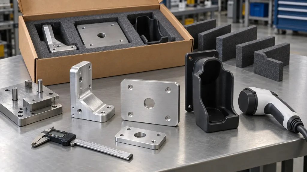
Introduce a Four-Interface Acceptance Framework
Use the following framework to separate supplier inspection from installation validation:
| Interface | Component acceptance focus | Separate validation input |
|---|---|---|
| Foundation to base plate | Specified hole pattern, seating faces and finish | Approved anchor layout and installation conditions |
| Charger to bracket | Datums, locating features and fastener access | Charger geometry and defined loads |
| Connector to holster | Approved fit, retention geometry and release clearance | Actual connector revision and handling conditions |
| Cable to guide or entry | Edge condition, passage geometry and attachment features | Cable requirements, routing and movement envelope |
Define Component Inspection and Assembly Checks
Inspect the critical features in their specified delivery condition, including post-fabrication or post-coating requirements. Use approved mating samples or functional fixtures where dimensional inspection alone cannot verify fit.
A successful fit check does not establish fatigue life, environmental durability or electrical-system performance.
Include the Information Suppliers Need
Send controlled CAD and drawings, material requirements and the intended manufacturing route. Add charger and connector references, critical datums and finish boundaries. State quantities, expected revisions and spare-part needs.
Define inspection records and protective packaging. Threaded features, exposed bonding pads and precision mating faces may require different protection during transport.
FAQs
Should an EV charger pedestal be machined or fabricated?
Evaluate the structure and precision interfaces separately. Formed sheet, extrusion or welded construction may suit the main body, while machining serves selected locating and mounting features. The decision depends on geometry, loads, quantity and the required delivery condition.
Which bracket features need tight tolerances?
Prioritize features that control functional alignment: locating holes, related mounting faces and specified offsets. Clearance slots and cosmetic edges may need different limits. Define datums and the assembled requirement before applying tight tolerances across the drawing.
Can connector holsters be CNC machined from plastic?
Yes. Machining can support prototype iteration and suitable low-volume components. The exact grade must suit the application’s loading, wear and exposure requirements. A machined sample does not automatically represent the behavior of a later injection-molded part.
Can one holster accommodate different connector models?
Possibly, but compatibility requires evaluation against each approved model and revision. Check retention, release access and cable-induced loading. Broad connector-family compatibility should not replace physical checks or controlled interface data.
How does powder coating affect holes and threads?
Deposited coating can reduce clearance and alter thread fit or seating. Identify masked features and specify which dimensions apply after finishing. Agree the inspection condition with the manufacturer rather than relying on an unspecified general allowance.
Does a machined component establish compliance for the charger?
No. Component acceptance confirms the agreed part requirements. Complete-equipment performance and installation suitability require their own verification. Keep responsibility for structural validation, electrical safety and site requirements explicit in the project documentation.
Conclusion: Purchase Components Around Their Interfaces
Machining EV charger pedestals is most useful when precision serves a defined interface within an appropriate manufacturing route. Apply the same discipline to brackets and holsters: control location where it matters, verify connector-specific geometry, and coordinate finishing with fit and service access.
Procurement can then compare proposals against the same delivery condition and acceptance plan. Keep component inspection distinct from complete-charger qualification and installation approval.
Send BOONA your CAD files, controlled drawings and mating-component information for a CNC machining DFM review. BOONA offers no minimum order quantity and a free DFM review. Include materials, finish requirements and quantities so the quotation can address the actual interfaces, manufacturing sequence and acceptance conditions before production begins.