
A clinical analyzer begins reporting unstable values after several sample cycles. The pump reaches its expected pressure, the valves actuate normally, and no external leak appears. During teardown, engineers find a small ridge where two drilled passages intersect inside the manifold. The ridge retains enough sample and rinse fluid to influence the next measurement.
This scenario shows why machining IVD and analytical instrument components requires planning around the measurement process. A part can meet its nominal dimensions while still creating carryover, optical drift, uneven heating, positioning errors or particle contamination.
Fluid blocks, optical mounts, heater plates and sample-handling assemblies each need a different machining and inspection strategy. Material selection, datum planning, internal deburring, surface treatment and functional testing all contribute to the reliability of the finished instrument.
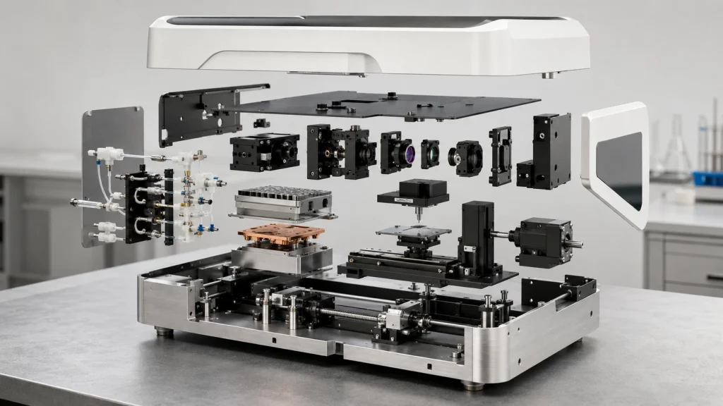
What Counts as an IVD or Analytical Instrument Component?
The FDA description of in vitro diagnostic products covers reagents, instruments and systems used to collect, prepare and examine specimens taken from the human body. The same FDA resource identifies 21 CFR Part 809 as the location of IVD labeling requirements.
Equipment in this category includes clinical chemistry analyzers, hematology systems, immunoassay platforms, molecular-diagnostic instruments and automated sample-preparation stations.
The scope of analytical instrument components extends further. Chromatography systems, spectrometers, environmental analyzers, laboratory robots and material-testing instruments often use comparable machined subsystems even though their regulatory obligations differ.
| Instrument subsystem | Typical machined components | Main manufacturing risks |
|---|---|---|
| Fluidics | Manifolds, valve blocks, pump heads, fittings | Leakage, burrs, trapped volume, contamination |
| Optics | Lens cells, detector mounts, optical benches | Alignment shift, runout, reflections |
| Thermal control | Heater blocks, cold plates, sensor pockets | Poor contact, flatness error, distortion |
| Sample handling | Carousels, grippers, pipetting plates | Runout, backlash, wear, collision |
| Structure | Baseplates, brackets, rails, housings | Datum transfer, vibration, stack-up |
A structural component may never contact a patient sample. Its movement can still change detector position, needle alignment or reaction temperature.
Material Selection for Machining IVD and Analytical Instrument Components
Material selection should begin by identifying whether each surface is wetted, non-wetted, optical, thermal, structural or part of a moving assembly.
Aluminum commonly serves in instrument baseplates, optical benches, detector housings, heat spreaders and lightweight robotic structures. It machines efficiently and conducts heat well, but designers must account for thermal expansion, coating thickness, electrical grounding and galvanic contact with other metals.
Stainless steel can support fluid manifolds, valve bodies, needle mounts, pump components and wear-resistant interfaces. A drawing that specifies only “stainless steel” leaves corrosion resistance, hardness and final surface condition unresolved. Reagent chemistry, wash fluids, disinfectants, temperature and passivation requirements should guide the grade selection.
PEEK and other engineering plastics may provide chemical resistance, electrical isolation or reduced moving mass. Their design risks include creep, moisture response, thread strength, burr formation and deformation under clamping.
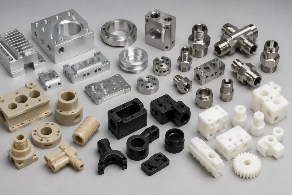
| Material | Typical analyzer use | Primary DFM concern |
|---|---|---|
| Aluminum | Frames, optical benches, heater blocks | Coating allowance and thermal movement |
| 316L stainless steel | Wetted manifolds and fittings | Burr control, passivation and tool access |
| PEEK | Chemical-resistant blocks and insulators | Creep, heat and thread design |
| POM | Guides and low-friction moving parts | Chemical compatibility and dimensional change |
| PTFE | Seals and resistant interfaces | Deformation and tolerance control |
For IVD instrument component machining, material review should include every fluid and cleaning chemical encountered throughout use, maintenance and storage.
Fluidic Manifolds and Internal Sample Paths
Fluidic manifold machining creates several risks that remain invisible during ordinary exterior inspection. Cross-drilled passages, blind intersections, valve seats, threaded ports and O-ring grooves can retain burrs or form pockets where fluid remains after a rinse cycle.
Potential carryover locations include:
- Misaligned passage intersections
- Deep counterbores
- Thread runouts
- Recessed sealing interfaces
- Abrupt internal transitions
- Partially removed burrs
The allowable trapped volume depends on sample size, viscosity, wash strategy and assay architecture. A universal dead-volume target would therefore be misleading.
Surface condition can also influence pressure loss. A 2026 study of CNC-micromilled PMMA microchannels used 264 machining instances to develop surface-roughness prediction models. The researchers then evaluated an 84-point friction-factor dataset and reported R² = 0.937 for the relationship between friction behavior and relative roughness.
Those figures describe a controlled research system rather than a universal manufacturing result. They show why machining parameters, channel morphology and cleaning requirements deserve attention in small analytical flow paths.
A manifold drawing should define internal burr acceptance, cleaning requirements and any leak or pressure-decay test. The test note also needs a medium, pressure or vacuum level, stabilization time, duration and allowable loss.
Optical and Thermal Instrument Components
Optical instrument component machining includes lens barrels, filter holders, detector carriers, laser housings, flow-cell mounts and optical benches. Their performance depends on relationships between bores, datums and mounting faces rather than on individual linear dimensions alone.
A stable datum strategy reduces accumulated error. Critical optical bores and locating faces may benefit from machining in one setup, especially where perpendicularity, concentricity and detector position control the optical path.
Surface treatment introduces another variable. Black anodizing may reduce visible reflections, although its optical behavior varies with wavelength, surface condition and angle. Precision seats, grounding points and locating bores may require masking. Coating buildup inside a bore can shift the installed lens or detector.
Thermal components present different risks. Heater blocks, cold plates, reaction plates and sensor pockets rely on contact flatness, sensor position, material conductivity and interface pressure. Internal-channel machining can release residual stress and move a broad contact face.
A temperature-uniformity requirement cannot be translated directly into a single machining tolerance. The equipment designer should connect thermal performance to wall thickness, contact geometry, sensor location and the control system. Drawings must also state whether dimensions apply before or after coating, polishing or passivation.
Sample Handling and Laboratory Automation
Automated analyzers use carousels, rack locators, pipetting-head plates, grippers, encoder brackets, rotor hubs and motor mounts. These components determine whether a tube, cuvette or microplate repeatedly reaches the required position.
Dimensional accuracy and motion repeatability measure different properties. A carousel may match its CAD model while producing inconsistent sample locations because of bearing clearance, hub runout, flexible mounting or assembly preload.
A 2024 study of robotic microplate handling evaluated a robot arm using a custom finger and a measuring platform built from aluminum frames and digital gauges. The researchers added artificial positional offsets and repeated the transfer 125 times at each condition. They examined offsets across 1.80–2.30 mm in one direction and 2.10–2.20 mm in the other, using finer evaluation intervals of 0.1 mm and 0.05 mm.
The study illustrates a useful inspection principle: repeated-position functions need repeated-position tests. A dimensional report for a hub bore or mounting pattern cannot reveal backlash, wear or preload changes across a complete motion cycle.
Designers should identify which features control tube pickup, barcode reading, needle alignment and sensor triggering. A consistent datum system should connect those features through the assembly.
DFM for Machining IVD and Analytical Instrument Components
Compact analyzers often combine angled fluid ports, sensor pockets, internal threads, sealing lands and mounting features in a single block. Integration can reduce assembly count, but it also increases tool-access, deburring and inspection difficulty.
A practical DFM review should ask:
- Can tools reach every passage intersection?
- Can internal burrs be inspected after machining?
- Can recessed channels be flushed and dried?
- Will long tools deflect inside deep pockets?
- Are thin walls left between nearby ports?
- Can sealing surfaces be protected during deburring?
- Are critical dimensions inspectable after coating?
- Can the part be serviced without damaging adjacent components?
Combining several features into one block also raises the cost of rejection. One damaged thread or inaccessible burr can make the entire component unusable.
Separating a complex design into controlled subcomponents may improve cleaning, inspection and maintenance. The best choice depends on sealing strategy, alignment requirements and the number of assembly interfaces introduced.
BOONA precision machining service can support early review of datums, tolerances and inspection access. Parts with angled channels or features across several faces may also benefit from 5-axis CNC machining.
💡 Pro Tip: Complete the cleaning and inspection plan before freezing an integrated manifold design. A feature that cannot be reached by a tool, gauge, borescope or cleaning process may require a geometry change.
Surface Finish, Cleaning and Particle Control
A drawing should separate four requirements:
- Cosmetic appearance
- Fluid-contact surface condition
- Optical surface behavior
- Final cleanliness
Bead blasting can create a consistent matte exterior. Inside a narrow channel or optical cavity, retained media and increased roughness may become functional concerns. Drawings should identify areas where blasting, polishing or coating is prohibited.
Passivation, electropolishing, anodizing and mechanical polishing also require surface-specific notes. Sealing lands, valve seats, electrical contacts and precision bores may need masking. Dimensions around treated features should state whether they apply before or after finishing.
ISO 14644-1 classifies air cleanliness by airborne-particle concentration for specified particle sizes. ISO 14644-5:2025 addresses operational controls for maintaining cleanroom conditions.
These standards should appear in a purchase specification only where the customer requires a defined controlled environment. A visually clean part does not automatically meet a particle, residue or surface-contamination requirement.
Final packaging also matters. Cleaned components can become recontaminated through exposed foam, unsuitable bags, uncontrolled handling or contact with unclean inspection fixtures.
Inspection for Machining IVD and Analytical Instrument Components
Inspection methods should follow the component’s function.
A CMM may suit optical mounting patterns and baseplate datums. Magnified inspection or optical measurement may be more appropriate for small channels and edges. Bore gauges, thread gauges, roughness instruments and functional fixtures support other requirements.
Typical controls include:
- Flatness and perpendicularity
- Bore position and runout
- Sealing-land condition
- Thread verification
- Surface-roughness measurement
- Leak or pressure-decay testing
- Repeated-position testing
- Particle or residue checks where specified
The phrase “NIST traceable” requires careful use. The NIST guidance on metrological traceability defines traceability through a documented, unbroken chain of calibrations, with each calibration contributing to measurement uncertainty. Referencing a NIST number alone does not establish a complete traceability claim.
ISO/IEC 17025:2017, reviewed and confirmed in 2023, defines requirements for the competence, impartiality and consistent operation of testing and calibration laboratories. It applies to laboratories and should not be presented as an automatic quality status for every machining supplier that owns calibrated equipment.
For precision machining laboratory equipment, inspection plans should connect every reported result to a drawing requirement and a suitable measurement method.
Application Example: Micro-Milled Analytical Flow Chip
A published microfluidic project shows how small dimensions change the manufacturing plan.
The researchers produced channels measuring 125 µm wide, 50 µm deep and 25.4 mm long, with 2 mm spacing. Their 2024 study of rapid microfluidic fabrication by micro-milling addressed material preparation, channel machining and final chip assembly.
At 125 µm width, a small burr can occupy a meaningful portion of the flow area. Depth variation changes the hydraulic cross-section, while roughness can affect resistance and filling behavior. The cover interface must seal without collapsing or distorting the channel.
A suitable control plan for this type of component would address:
- Channel width and depth
- Edge condition under magnification
- Port location
- Surface cleanliness
- Cover alignment
- Bonding or sealing condition
- Functional flow after assembly
The likely failure mode is a partially restricted or poorly sealed channel rather than an obvious external dimensional defect. Standard caliper inspection would provide little useful evidence at this scale.
This published example is not a BOONA customer project. It demonstrates why microfluidic and analytical components may require magnified metrology and assembly-level testing beyond conventional machined-part inspection.
Quality and Regulatory Boundaries
The finished-device manufacturer remains responsible for assay performance, validation, regulatory submissions and device release. A component supplier supports that system through controlled drawings, material records, documented inspection and managed special processes.
The FDA’s Quality Management System Regulation became effective on February 2, 2026. It amended the device current good manufacturing practice requirements in 21 CFR Part 820 and incorporated ISO 13485:2016 by reference.
ISO 14971:2019 provides a risk-management process for medical devices, including IVD medical devices. Component-related risks may include leakage, contamination, optical misalignment, thermal instability and incorrect sample positioning. The device manufacturer determines the complete risk analysis and acceptance criteria.
Supplier records may include:
- Material and lot certificates
- Approved drawing revisions
- First-article inspection reports
- Special-process certificates
- Cleaning records where required
- Calibration records
- Nonconformance documentation
- Change notifications
- Matched-component identification
BOONA should be positioned as a supplier of precision-machined development and production components. Finished-device validation, assay performance and regulatory release remain under the device manufacturer’s control.
FAQs
What components are CNC machined for IVD analyzers?
Common examples include fluidic manifolds, valve blocks, optical benches, detector mounts, heater blocks, cold plates, sample carousels, pipetting-head plates, structural frames and inspection fixtures.
Which material is best for an IVD fluidic manifold?
The choice depends on reagent chemistry, wash fluids, operating pressure, temperature, cleanliness and the customer’s material specification. Stainless steel and engineering plastics suit different operating conditions.
How can machining reduce sample carryover?
Controlled passage intersections, reduced trapped volume, internal deburring, defined cleaning and functional flow testing can reduce locations where sample or rinse fluid remains.
Why is optical-bench machining difficult?
Optical alignment depends on datum stability, bore relationships, thermal expansion, coating thickness and assembly stack-up. A simple linear tolerance may not control those combined effects.
Should analytical instrument components be manufactured in a cleanroom?
Only where the product, manufacturing process or purchase agreement requires a defined controlled environment. Cleanroom classifications should not be claimed automatically.
What should an IVD component drawing include?
It should define material, final condition, wetted surfaces, critical datums, sealing geometry, burr limits, surface finish, cleaning, inspection, traceability and functional test requirements.
Conclusion: Machine Every Component Around the Measurement
Successful machining IVD and analytical instrument components begins with understanding how each part influences the final measurement.
Fluidic channels require controlled intersections, burr removal and cleanability. Optical mounts need stable datums and predictable thermal behavior. Heater blocks depend on contact geometry and sensor position. Sample-handling assemblies require repeatable movement as well as dimensional accuracy.
Inspection should include flow, leak, alignment or positioning tests where conventional dimensional measurements cannot confirm full function. Materials, finishing and documentation must also match the requirements defined by the finished-device manufacturer.
Send BOONA your controlled CAD files, drawings, material specifications, fluidic or optical requirements and required inspection records through the CNC machining service. An early DFM review can identify tool-access, trapped-volume, coating, cleaning and metrology risks before production.


