
An abutment seats into a prototype implant connection and the retaining screw reaches its specified assembly torque. The assembly still shows a small amount of rotational movement. Diameter measurements look normal, so the engineering team checks the connection as a complete system and finds small differences in taper alignment, indexing geometry and the relationship between the screw axis and seating surface.
This is where dental implant component machining becomes more demanding than simply holding a tight diameter.
Implant interfaces, miniature screws, abutments, drivers and reusable dental instruments depend on geometric relationships between several small features. Material specification, datum strategy, burr control, surface condition and functional inspection all influence how those parts work together.
The machining plan should therefore follow the function of the component, especially where a few micrometers or a small angular difference can change seating, rotational freedom or instrument engagement.
Which Dental Implant and Instrument Components Are Machined?
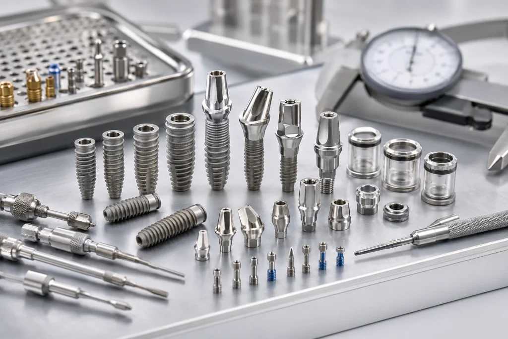
Dental implant systems contain several different machined component families.
Implant-related development hardware can include abutments, healing components, connection samples, prosthetic screws, laboratory analogs and test fixtures. Instrument systems may contain drivers, drill stops, guide sleeves, depth-control components, ratchet interfaces and coupling shafts.
Each group presents a different manufacturing priority.
| Component family | Critical feature | Primary manufacturing risk |
|---|---|---|
| Implant connection | Taper, hex or indexing geometry | Axis error and rotational clearance |
| Abutment | Connection and prosthetic geometry | Datum transfer and thin-wall distortion |
| Prosthetic screw | Miniature thread and seating face | Thread damage and runout |
| Implant driver | Engagement feature | Wear and inconsistent torque transfer |
| Guide sleeve | Precision bore | Bore alignment and surface condition |
| Rotating instrument | Shaft and working feature | Runout and coaxial error |
The distinction between development hardware and a released medical device also matters.
A precision-machined connection sample can support fit testing or engineering evaluation without being a clinically usable implant. Final implant systems require approved materials, biological evaluation, mechanical validation, sterilization controls and the applicable regulatory release process.
That boundary should remain clear throughout supplier documentation and marketing language.
Materials for Dental Implant Component Machining
Material selection should begin with the controlled device specification.
The FDA overview of dental implant systems notes that most dental implant systems use titanium or zirconium oxide and explains that implant materials are evaluated using international consensus standards and biocompatibility testing.
For metallic implant-related components, the exact titanium grade must appear on the engineering documentation.
ASTM F67-24 covers four grades of commercially pure titanium used for manufacturing surgical implants. ASTM F136-26 covers wrought annealed Ti-6Al-4V ELI for surgical implant applications. ISO 5832-11:2024 specifies wrought Ti-6Al-7Nb.
These standards define material requirements. They do not automatically qualify every component machined from those materials as an approved implant.
For titanium dental implant components, drawings should also define material condition, certification requirements and any lot or heat traceability needed by the customer’s quality system.
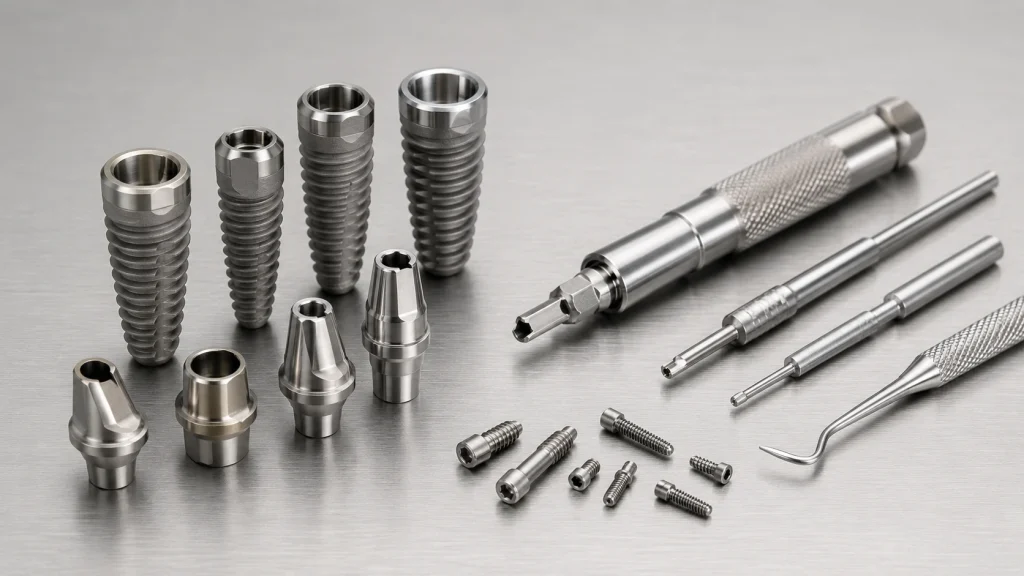
Reusable dental instruments often use a different material framework. Stainless steels may suit drivers, guides and other reusable components where strength, corrosion performance and repeated mechanical engagement matter.
Development parts produced from titanium can also be reviewed through BOONA titanium CNC machining capabilities according to customer-controlled material specifications.
Implant Connections and Anti-Rotation Features
Connection geometry is one of the most critical parts of dental implant component machining.
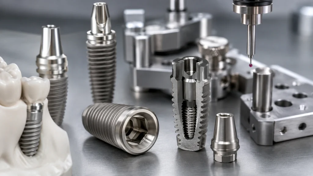
Internal hexes, external hexes, conical interfaces, indexing lobes and other anti-rotation features all depend on their relationship with the central axis and seating surface.
A 2023 Journal of Prosthetic Dentistry study evaluated 150 implant-abutment assemblies across five implant systems, using 30 assemblies for each system. Mean rotational freedom ranged from 0.05° to 2.49°, with statistically significant differences among the connection designs in the study of implant-abutment rotational freedom.
Those figures describe the five systems tested and should never become generic machining tolerances.
Their engineering significance lies in the interaction between features.
A taper may have the correct nominal angle while its axis shifts relative to the thread. An indexing feature may measure correctly but sit slightly off-center. A shoulder may meet its thickness specification while lacking perpendicularity to the functional axis.
A useful datum structure therefore considers the connection as a group:
- Central implant or abutment axis
- Connection taper
- Anti-rotation feature
- Screw or thread axis
- Seating shoulder
Reducing unnecessary repositioning can help preserve these relationships. Complex multi-face components can be reviewed through BOONA 5-axis CNC machining service where the geometry benefits from fewer setups.
Small Threads, Prosthetic Screws and Driver Engagement
Miniature threaded components concentrate several important features into a very small area.
Thread pitch represents only one part of the functional system. Assembly behavior also depends on pitch diameter, lead, flank condition, thread runout, thread-axis position and the relationship between the thread and seating surface.
Small burrs deserve particular attention. Damage that appears minor on a large industrial fastener may occupy a significant portion of a dental screw flank or driver feature.
Driver recesses create similar concerns. Hexagonal, lobed or proprietary geometries transfer torque through limited contact areas. Rounded corners or excess clearance can concentrate contact on fewer surfaces and change engagement behavior.
A 2024 systematic review evaluated 172 specimens, consisting of 86 zirconia and 86 titanium abutments. The researchers reported greater implant-connection wear and misfit with zirconia abutments, while titanium abutments generally produced a better fit. The systematic review of titanium and zirconia abutments also concluded that manufacturing method can influence interface fit.
For dental abutment machining, this reinforces the need to control the complete connection rather than assigning one overall tolerance to the entire component.
Customer-specific or proprietary interfaces should always be manufactured from controlled drawings and approved specifications.
Surface Condition and Finishing Boundaries
Mechanical connection surfaces and biologically active implant surfaces require different controls.
Implant-abutment tapers, screw seats, guide bores and driver interfaces primarily depend on dimensional stability, controlled surface condition, clean edges and protection from handling damage.
A polishing process can change these relationships if it removes material from a taper or rounds a small indexing corner. Coating thickness can create a similar effect where tight fits are involved.
Drawings should therefore identify:
- Surfaces that may be polished
- Features that require masking
- Dimensions that apply after finishing
- Controlled edge breaks
- Surfaces that must remain untouched
- Final cleaning requirements
Implant surfaces intended to influence tissue response belong to another process category. Blasting, acid treatment, porous coatings or other surface modifications intended to affect osseointegration require device-specific validation.
Ordinary CNC finishing should not be represented as equivalent to a validated biological implant-surface process.
This distinction protects both engineering clarity and regulatory positioning. A supplier can machine a precise implant interface while the medical-device manufacturer remains responsible for validating any surface modification intended to affect biological performance.
Machining Reusable Dental Instrument Components
Dental instrument machining introduces wear, repeatability and cleanability requirements that differ from implant-related hardware.
Reusable drivers, guide sleeves, depth-control components, couplings and ratchet parts may experience repeated mechanical engagement and repeated cleaning cycles.
ISO 21850-1:2020, confirmed as current in 2025, specifies stainless steels commonly used in the manufacture of single-use and reusable dental instruments. It also explicitly excludes long-term intraoral devices such as implants.
Instrument design should consider:
- Engagement-surface wear
- Shaft runout
- Coupling clearance
- Edge damage
- Burr traps
- Cleaning access
- Corrosion-related material requirements
A driver can remain dimensionally acceptable while its contact corners gradually become rounded through repeated engagement. Likewise, a precision guide sleeve can develop functional problems if its bore and outer reference lose alignment.
Cleaning geometry deserves attention during DFM. Deep blind corners, unnecessary crevices and inaccessible recesses may retain residue even where machining access is straightforward.
Functional gauges can therefore provide useful information in addition to dimensional measurement. A controlled mating interface may reveal excess looseness more directly than an isolated width or diameter measurement.
Runout, Coaxiality and Rotational Accuracy
Rotational components expose geometric relationships that a diameter measurement cannot describe.
A shaft may have the correct diameter while its working end rotates eccentrically. A guide sleeve can have both its inner and outer diameters within specification while the axes remain misaligned.
Drawings for rotational dental components may therefore need controls for:
- Runout
- Coaxial relationships
- Perpendicularity
- Shaft straightness
- Position of engagement features
- Stop-face orientation
The required limits should come from the assembly and instrument function. Extremely tight diameter tolerances do little good if the diameter does not lie on the functional axis.
💡 Pro Tip: Define the functional datum axis before tightening individual diameter tolerances. A precisely machined diameter can still produce substantial runout at the working feature when the axis relationship is poorly controlled.
Inspection setup matters too. If the component rotates during use, measuring it around the same functional axis can provide better information than inspecting unrelated surfaces individually.
The machining sequence should preserve that axis through subsequent operations, finishing and final inspection.
DFM for Small Dental Implant Components
Small dental parts can place several difficult features within only a few millimeters of material.
Typical concerns include:
- Deep internal connection cavities
- Miniature threads
- Narrow slots
- Thin walls
- Long small-diameter bores
- Internal tapers
- Cross holes
- Difficult deburring locations
Tool access is only the first question.
A slender cutter may reach a deep indexing cavity but lack enough rigidity to maintain the intended geometry. Chips may become difficult to evacuate from a miniature blind feature. A cross-hole intersection can create a burr that remains almost invisible during ordinary inspection.
Workholding adds another constraint. When most exterior surfaces form part of the functional geometry, the process may leave very little space for secure clamping.
Thin sections can also move under clamping pressure or after material removal.
A DFM review should therefore consider machining, workholding, deburring, cleaning and inspection at the same time.
Designers should also avoid specifying unnecessarily tight tolerances on every feature. Concentrating control on mating geometry, functional axes and seating surfaces can improve manufacturability while protecting the features that actually influence system performance.
Inspection of Dental Implant and Instrument Components
Inspection should reflect how the component functions in an assembly.
Depending on feature size and geometry, suitable methods may include:
- Optical or vision measurement
- CMM inspection
- Pin and bore gauges
- Thread gauges
- Runout measurement
- Surface roughness measurement
- Profile inspection
- Functional mating gauges
Interface inspection can also reveal behavior that isolated dimensions cannot show.
A 2023 micro-CT study examined prefabricated and customized titanium abutments assembled at 25 N·cm. Researchers collected 24 microsections per scan and measured the interface at four levels. Reported microgap values ranged from 0.1 to 3.7 µm in one group and 0.1 to 4.9 µm in the other in the micro-CT implant-abutment study.
The researchers also reported no detectable microgap in 90% of specimens in one group and 70% in the other under their experimental conditions.
These study values should not become generic production acceptance criteria.
They show why assembled-interface behavior may deserve its own inspection method. Seating depth, rotational freedom, contact and functional engagement can complement conventional dimensional reports.
Final inspection should also follow any finishing process capable of changing a functional surface.
ISO 14801 and Dental Implant Fatigue Testing
Machining consistency supports repeatable test specimens, while fatigue behavior remains a system-level property.
ISO 14801:2016 specifies dynamic testing for single-post endosseous dental implants in combination with prefabricated prosthetic components.
ISO describes the method as particularly useful for comparing implants with different designs or sizes under specified worst-case loading conditions.
The standard also establishes an important boundary. It does not measure the fundamental fatigue properties of the raw material, and its test results do not predict actual in-vivo implant performance.
As of August 2026, ISO 14801:2016 remains the published edition and carries the status International Standard to be revised.
ISO has already opened the fourth-edition development project. ISO/AWI 14801 entered the preparatory stage on June 1, 2026.
Medical-device manufacturers should therefore identify the controlled revision in test documentation instead of using a general reference to “ISO 14801.”
For machining teams, the practical role is to provide dimensionally consistent specimens and controlled interfaces according to the customer’s test configuration. Passing dimensional inspection alone does not demonstrate implant-system fatigue performance.
Application Example: Measuring an Implant-Abutment Microgap
The 2023 micro-CT research provides a useful example because it examined micron-scale interface behavior rather than a dramatic component fracture.
Researchers tightened the tested abutments to 25 N·cm and examined 24 microsections from each scan at four interface levels.
Measured gaps reached 3.7 µm in one group and 4.9 µm in the other, while many specimens showed no detectable gap under the study conditions.
For a component engineer, several manufacturing variables can influence this kind of interface:
- Taper angle and profile
- Connection-axis alignment
- Seating depth
- Surface condition
- Microscopic burrs
- Contamination between mating surfaces
- Dimensional variation between two components
The lesson is not to copy 3.7 or 4.9 µm onto a production drawing.
Instead, the device manufacturer should define the required interface performance and translate that requirement into component tolerances, mating gauges, assembly conditions and validation tests.
A conventional dimensional report may verify each individual feature while leaving the final mating relationship untested.
This is a published research example and does not represent a BOONA customer project or a BOONA capability claim.
Quality and Regulatory Boundaries
Dental implant development requires a clear division of responsibility between component manufacturing and finished-device validation.
A machining supplier can support customer-defined development parts, instrument components, test samples and production hardware. The medical-device manufacturer remains responsible for material qualification, biological evaluation, sterilization validation, implant-system mechanical testing, labeling, regulatory submissions and final release.
Useful component records may include:
- Material certificates
- Heat or lot identification
- Controlled drawing revisions
- First-article reports
- Dimensional inspection records
- Special-process certificates
- Nonconformance records
- Change notifications
- Matched-component identification where required
Purchasing documents should avoid vague descriptions such as “implant titanium” or “medical stainless.”
The exact material standard, grade, condition and certification requirements should appear on the controlled documentation.
Likewise, terms such as “FDA-approved machining,” “ISO 14801-certified part” or “implant-approved titanium” can overstate what an individual standard or machining process establishes.
Teams working earlier in the design cycle can also review BOONA guide to medical implant prototyping with 3D printing and CNC before transitioning a design into a controlled manufacturing pathway.
FAQs
What titanium is used for dental implant components?
Commercially pure titanium and titanium alloys such as Ti-6Al-4V ELI or Ti-6Al-7Nb can be used depending on the device specification. The exact material should come from the controlled design documentation.
Why is dental implant connection machining difficult?
Tapers, threads, indexing features, seating surfaces and the central axis must work together. Small angular and positional variations can affect seating and rotational freedom.
What tolerances are required for dental implant machining?
There is no universal tolerance for dental implant components. Requirements depend on component size, mating geometry, interface design, manufacturing process and validated system performance.
What stainless steel is used for dental instruments?
ISO 21850-1:2020 identifies stainless steels commonly used to manufacture single-use and reusable dental instruments. The specific grade should follow the approved instrument design.
What does ISO 14801 test?
ISO 14801 defines dynamic loading testing for certain endosseous dental implant and prosthetic-component assemblies. It supports comparative testing under controlled conditions and does not predict clinical performance.
What should a dental implant component drawing include?
It should define material, functional datums, critical connection geometry, threads, surface condition, burr requirements, finishing condition, inspection methods, traceability and any required functional mating tests.
Conclusion: Control the Dental Connection as a System
Successful dental implant component machining depends on the relationship between the connection geometry, thread axis, seating surfaces, functional datums and mating components.
Implant-related hardware requires tightly controlled interfaces and documented materials. Reusable dental instruments add requirements for runout, wear, engagement and cleanability. Functional gauges or assembled-interface inspection can supplement dimensional reports where individual measurements do not fully represent component behavior.
Fatigue performance, biological safety, sterilization validation and regulatory approval remain responsibilities of the finished-device manufacturer’s validated system.
Send BOONA your controlled CAD files, material specification, connection requirements and inspection criteria through the CNC machining service for an early manufacturability review before production.


