
A replacement pressure sensor arrives with a male “1/4-inch” connection. The manifold drawing also specifies a 1/4-inch port, so the connection appears straightforward. During assembly, the fitting turns twice, starts to bind, and later leaks despite the addition of more sealant. This is a common consequence of NPT vs BSPP vs BSPT confusion.
Nominal sizes can look similar while taper, pitch, thread profile, and sealing geometry remain incompatible. Forcing the connection can deform thread flanks, damage the port, contaminate the fluid circuit, or create a joint that fails under pressure.
Reliable pipe thread identification requires several checks. Engineers need to establish the governing standard, determine whether the thread is tapered or parallel, measure its pitch, confirm the flank angle, and identify where the connection creates its seal.
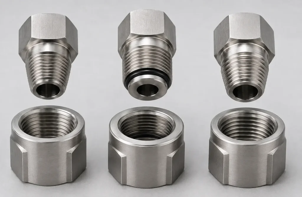
What NPT vs BSPP vs BSPT Actually Means
Each pipe thread family combines a defined geometry with a particular sealing strategy. The word “pipe” does not make the systems interchangeable, and a nominal size such as 1/4 inch does not equal the measured outside diameter.
NPT
National Pipe Taper threads follow ASME B1.20.1 for general-purpose inch pipe threads. NPT uses a 60-degree included thread angle and a 1:16 taper on diameter. Both the male and female members are tapered.
As the fitting advances, increasing flank interference creates mechanical engagement. Most applications also require a compatible tape or liquid sealant to fill the helical leakage path.
A typical callout is 1/4-18 NPT. The first value identifies the nominal pipe size, while 18 specifies the threads per inch.
BSPP
British Standard Pipe Parallel threads generally follow ISO 228-1. Internal and external threads are parallel, the included angle is 55 degrees, and the Whitworth-style profile has rounded roots and crests.
BSPP commonly uses a G designation, such as G 1/4. ISO 228-1 covers nominal sizes from 1/16 through 6 and specifies that the thread itself does not create the pressure-tight seal. An O-ring, bonded washer, gasket, machined seat, or similar sealing element performs that function.
BSPT
BSPT commonly refers to pressure-tight thread forms defined by ISO 7-1. They use a 55-degree profile and a 1:16 taper where a tapered member applies.
ISO 7-1 distinguishes three callouts:
R: tapered external threadRc: tapered internal threadRp: parallel internal thread intended to mate with an R external thread
Because an Rp port is parallel, specifying “BSPT female” alone can leave the required geometry unclear. Controlled drawings should use R, Rc, or Rp.
NPT vs BSPP vs BSPT Comparison Table
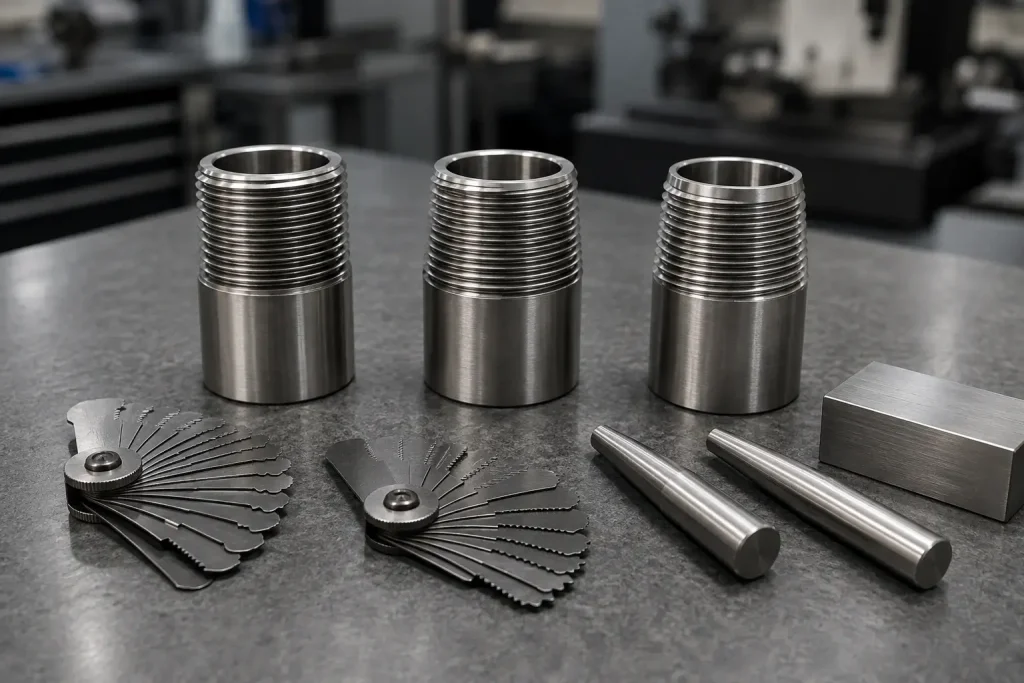
The fastest comparison begins with the thread profile, taper, and seal location. Pitch alone can mislead inspectors because some NPT and BSP sizes have the same number of threads per inch.
| Feature | NPT | BSPP | BSPT |
|---|---|---|---|
| Governing standard | ASME B1.20.1 | ISO 228-1 | ISO 7-1 |
| Common designation | NPT | G | R, Rc, or Rp |
| Included thread angle | 60° | 55° | 55° |
| Thread form | Tapered male and female | Parallel male and female | Tapered external; tapered or parallel internal |
| Taper rate | 1:16 on diameter | None | 1:16 where tapered |
| Primary seal location | Thread interference with suitable sealant | O-ring, washer, gasket, or seat | Thread engagement with suitable sealant |
| Example callout | 1/4-18 NPT | G 1/4 | R 1/4 or Rc 1/4 |
| Direct interchangeability | No | No | No |
For example, 1/4 NPT uses 18 threads per inch, while G 1/4 and R 1/4 use 19. At the 1/2-inch size, NPT and BSP both use 14 threads per inch. Their flank angles, basic diameters, crest shapes, and sealing systems still differ.
A drawing callout such as “1/4 pipe thread” therefore leaves the manufacturer without enough information to machine or inspect the connection correctly.
A Practical Pipe Thread Identification Process
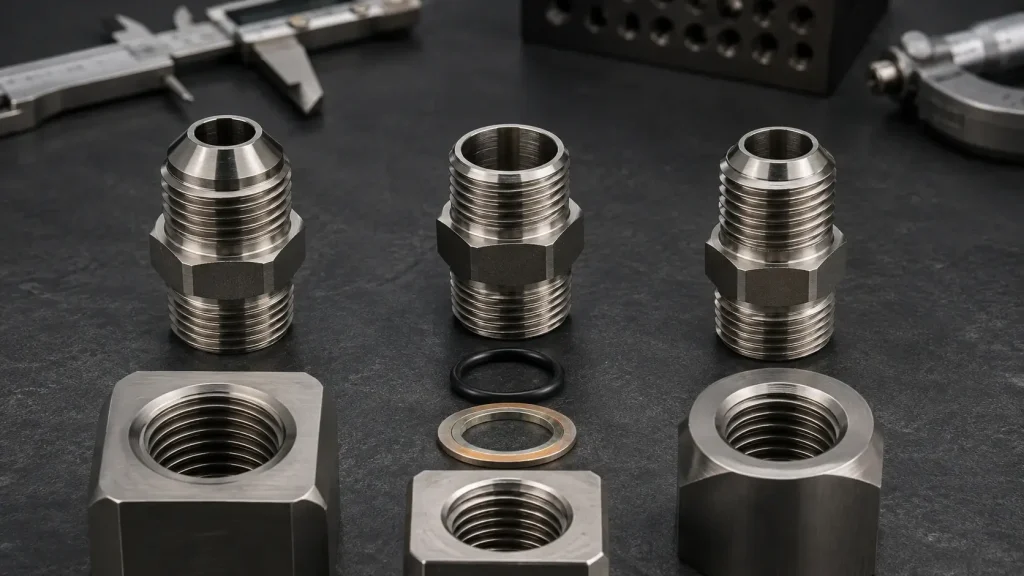
A dependable identification process moves from visible evidence to dimensional confirmation.
1. Check the markings and documentation
Look for NPT, G, R, Rc, or Rp on the component, drawing, equipment manual, or packaging. A standards-based callout provides stronger evidence than descriptions such as “1/4 gas thread” or “British fitting.”
2. Locate the intended seal
A flat port face, O-ring groove, conical seat, or bonded-washer land indicates that the thread primarily retains the fitting while a separate feature creates the seal. This configuration commonly points toward BSPP or another straight-thread system.
3. Check for taper
Measure the major diameter near the first complete thread and again farther along the fitting. NPT and tapered R threads increase in diameter toward the fitting body. BSPP remains substantially constant.
Short engagement lengths, chamfers, and incomplete threads can affect caliper readings, so taper measurement should support other evidence.
4. Measure the pitch
Use a thread-pitch gauge. A 1/4-inch example illustrates its value: NPT uses 18 TPI, while BSP uses 19 TPI.
5. Confirm the profile angle
NPT uses a 60-degree profile. BSPP and BSPT use a 55-degree Whitworth form. An optical comparator, profile projector, or dedicated gauge provides better evidence than visual inspection.
6. Use the correct gauge
Complete the identification with a calibrated plug or ring gauge for the suspected standard. Trial assembly with an available fitting can damage both parts and does not establish conformity.
Why Similar Pipe Threads Cannot Be Interchanged
Two connections may share a nominal size and even the same pitch while contacting across only small sections of their thread flanks.
A 1/2 NPT fitting and a G 1/2 component both use 14 threads per inch. NPT still has a 60-degree tapered profile, while G 1/2 has a 55-degree parallel profile and expects a separate sealing feature.
During forced assembly, the first threads may deform enough to create the sensation of engagement. Continued tightening concentrates stress at a few contact points. Galling, cracked plating, damaged port threads, unstable clamp load, and an unpredictable leakage path can follow.
Sealant may temporarily conceal the geometry problem. It cannot restore the specified flank contact or create the required sealing face.
Even correctly matched pipe threads require controlled installation. A 2025 peer-reviewed study of 27 NPT-threaded fire-suppression assemblies examined 1-, 1.5-, and 2-inch elbows and tees under quasi-static deformation. Leakage at the pipe-to-fitting interface was the primary failure mode.
The research concerned matched NPT joints under external movement, so it does not represent an NPT/BSP mismatch. It demonstrates that compatibility, assembly control, support conditions, and external loading all influence connection performance.
Where two systems must meet, specify an adapter with the correct thread and sealing method on each side.
Sealing Methods for NPT, BSPP, and BSPT
The thread designation should lead directly to the intended sealing method.
NPT joints generate radial interference as the tapered threads advance. Most applications use an approved sealant to fill the spiral leakage path and lubricate assembly. The selected tape or compound must suit the fluid, temperature, pressure, fitting material, cleanliness requirements, and applicable industry rules.
Excess tape or paste can enter pneumatic and hydraulic passages. Assembly instructions should therefore control the product, application position, amount, and tightening method.
BSPP connections use parallel threads primarily for retention. A shoulder, flange face, port spotface, O-ring, gasket, bonded washer, or cone creates the seal. Spotface flatness, perpendicularity, groove geometry, and available seal compression may have more influence on leakage than additional thread engagement.
BSPT connections form pressure-tight threaded joints through the applicable R-to-Rc or R-to-Rp engagement, normally with a suitable sealant. Assembly specifications should define the permitted thread combination and tightening method.
Pro Tip: Put the sealing element directly on the drawing. A G 1/4 callout identifies the thread, while the drawing must also define the O-ring, washer, sealing face, groove, finish, and inspection requirements.
Leak testing should represent the actual joint. Pressure, fluid, temperature, dwell time, and cycling conditions may all influence the result.
Manufacturing NPT, BSPP, and BSPT Ports
Manufacturing begins with a complete callout. The model and drawing should agree on the standard, nominal size, internal or external form, thread depth, sealing feature, runout allowance, and inspection condition.
NPT and tapered BSP forms can be produced using tapered taps, thread milling, or single-point cutting. The choice depends on material, quantity, machine access, thread size, and part geometry.
Thread milling allows diameter adjustment and controlled engagement while reducing the risk associated with extracting a large tap from an expensive component. Single-point CNC turning services suit many rotational adapters, fittings, and external tapered threads.
BSPP ports require accurate parallel threads together with controlled sealing geometry. For an O-ring or bonded washer connection, the spotface must remain flat and sufficiently perpendicular to the thread axis. Burrs at the first thread or sealing land can cut an elastomer during assembly.
The threaded-hole standards guide from BOONA provides additional information about thread callouts, machining methods, inserts, and gauge-based inspection. The controlled project drawing still defines the individual part.
Surface finishing also requires planning. Anodizing, plating, paint, and conversion coatings can alter flank clearance or sealing surfaces. The drawing should state whether threads will be masked, chased, or inspected before or after finishing.
Blind ports need enough relief for tap lead, thread-mill runout, and chip evacuation without breaking into nearby fluid passages.
Inspection and Quality Control for Pipe Threads
A mating production fitting should not serve as the primary inspection gauge. Wear, coating variation, contamination, sealant residue, and unknown tolerances can make an unacceptable port appear functional.
For NPT, the specified tapered plug or ring gauge checks the thread relative to its reference plane. Inspectors should follow the relevant standard procedure and record the gauge position instead of reporting only “fits.”
Additional checks may address taper, crest condition, effective thread length, pitch diameter, and the position of incomplete threads.
BSPP inspection normally combines a suitable GO/NO-GO thread gauge with separate verification of the sealing surface. A thread may pass its gauge while a damaged spotface, incorrect O-ring groove, or excessive perpendicularity error still causes leakage.
BSPT ports require gauges that match the R, Rc, or Rp form. A generic “BSP gauge” does not distinguish every tapered and parallel configuration.
A practical inspection plan should define:
- Gauge standard and exact size
- Calibration and gauge-wear status
- Acceptable gauge position or limit
- Inspection before or after coating
- Sealing-land dimensions and surface requirements
- Deburring and cleanliness criteria
- Leak- or pressure-test method where required
Results should remain traceable to the drawing revision and manufacturing lot. This prevents parts manufactured correctly to an obsolete revision from reaching assembly.
Application Case: An Incompatible Fitting Found at 10 Bar
A 2025 Energy Institute incident report documents an offshore flushing operation in which a hose-to-valve connection began leaking at approximately 10 bar. The crew depressurized the system, yet the connection continued leaking at ambient pressure.
Investigators found that a Parker-style fitting had been forced into an incompatible 3/4-inch, or approximately 1.9-centimeter, NPT fitting. The forced connection damaged the threads.
The intended full working pressure for the task was 50 bar. A separation at that pressure could have created projectile and pressure-injury hazards.
The report does not identify the other fitting as BSPP or BSPT. Describing the incident as a confirmed NPT-to-BSP mismatch would therefore exceed the published evidence. The event still demonstrates a clear identification and compatibility failure: initial engagement and additional tightening force did not establish that the two components shared a thread standard.
A more reliable maintenance process would separate identification from installation. Teams should verify component markings, measure the thread, confirm the intended seal, and compare the findings with controlled equipment documentation.
For OEM programs, traceable drawings and approved component lists reduce the chance that a visually similar substitute reaches assembly. Unidentified adapters should remain segregated until their specifications have been established.
What to Include in a Pipe-Thread RFQ
A complete RFQ prevents the machine shop, fitting supplier, and assembly team from interpreting the same port differently. Provide the 3D model together with a controlled drawing containing:
- Standard and designation, such as
1/4-18 NPT,G 1/4, orRc 1/4 - Internal or external thread requirement
- Thread depth and effective engagement length
- Runout and incomplete-thread limits
- Port orientation and datum relationship
- Sealing method and mating component
- Spotface, seat, groove, and finish requirements
- Material and heat-treatment condition
- Coating, masking, or post-finish gauge requirements
- Inspection gauge and reporting expectations
- Pressure, fluid, temperature, and cleanliness information
- Applicable customer or regulatory specifications
Avoid using “1/4 pipe,” “British thread,” or “standard air fitting” as the complete definition. These descriptions omit the geometry and sealing system.
For parts containing several port types, include a port schedule that maps each item number to its exact callout and mating fitting. Purchasing descriptions, inspection records, and assembly instructions should use the same terminology.
FAQs
Is BSPP the same as a G thread?
A G designation normally identifies an ISO 228 parallel pipe thread. The complete callout should still include the nominal size, applicable tolerance, and sealing details.
Is BSPT the same as an R thread?
R specifically identifies a tapered external ISO 7-1 thread. Rc identifies a tapered internal thread, while Rp identifies a parallel internal thread intended for a pressure-tight threaded joint.
Can an NPT fitting connect directly to a BSPT port?
Direct combination should be avoided. The 60- and 55-degree profiles differ, and the diameter or pitch may also differ. Use a correctly specified NPT-to-BSP adapter.
How can I distinguish BSPP from BSPT?
Check the callout and measure the diameter at two axial positions. BSPP remains parallel. An R or Rc thread changes diameter along its length. Confirm the result with the correct gauge.
Does BSPP require thread sealant?
BSPP normally seals through an O-ring, bonded washer, gasket, or seat. Applying sealant to parallel threads does not replace the specified sealing element.
What pipe-thread information belongs on a drawing?
Specify the governing standard, exact callout, internal or external form, thread depth, sealing geometry, coating state, inspection gauge, and pressure-test requirements.
Conclusion
NPT vs BSPP vs BSPT identification depends on four connected questions: Which standard defines the thread? Is it tapered or parallel? Does it use a 60- or 55-degree profile? Where does the joint create its seal?
NPT uses a 60-degree tapered form and normally relies on controlled interference with suitable sealant. BSPP uses a 55-degree parallel thread with a separate sealing element. BSPT describes ISO 7-1 pressure-tight forms using R, Rc, or Rp designations.
Similar nominal sizes, matching thread counts, or a few turns of apparent engagement do not establish compatibility. Measure first, verify with the correct gauge, and define the sealing method on the drawing. That sequence protects the threads, sealing surfaces, equipment, and personnel while giving manufacturing and quality teams one controlled definition of acceptance.
If your manifold, valve body, sensor adapter, or fluid-control component contains NPT, BSPP, or BSPT connections, send BOONA the CAD model, controlled drawing, mating-fitting details, and inspection requirements. The team can review thread geometry, tool access, sealing lands, coating allowances, and gauge strategy through its precision CNC machining services. Send your CAD to begin the technical review.


