A robot arm can move with perfect repeatability and still fail at the last 20 millimeters.
That is where the gripper touches the part.
If the jaw slips, the cycle fails. If the contact face marks the product, the part may be rejected. If the EOAT plate flexes, the robot may lose alignment. If a vacuum channel leaks, the robot may drop the workpiece halfway through a transfer. The robot may be accurate, fast, and well-programmed — but the automation cell still stops.
That is why CNC machining for robot grippers matters.
Robot grippers and end effectors are the final mechanical interface between the robot and the product. They need controlled contact geometry, stable mounting, repeatable locating features, suitable materials, clean surfaces, and enough stiffness to survive real production cycles.
For automation integrators, robotics engineers, EOAT designers, and sourcing teams, CNC machining is one of the most practical ways to make gripper fingers, custom jaws, EOAT plates, tool changer adapters, vacuum manifolds, sensor brackets, and low-volume end-effector parts before moving into larger production.
Why Robot Grippers and End Effectors Need CNC Machining
A gripper does not need to be complicated to be critical. It only needs to touch the product wrong once to stop a line.
Robot gripper machining is used when gripper parts need accurate mounting holes, repeatable contact surfaces, threaded features, dowel pin holes, vacuum channels, sensor mounting points, or clean assembly with pneumatic components. These are not always large parts. Many are small, but their function is direct and unforgiving.
A gripper finger that is 0.2 mm off may still look fine on a bench. During production, that same error can cause inconsistent gripping, part tilt, poor release, or uneven contact pressure. A vacuum plate with poor flatness may create leakage. A tool changer adapter with poor hole position may make the robot wrist interface unreliable.
The robotics market is moving toward more flexible automation. IFR reported that professional service robot sales grew 30% worldwide in 2023, with more than 205,000 units registered. Transportation and logistics robots alone reached nearly 113,000 units, up 35%. More robots in warehouses, production lines, labs, and service environments means more demand for reliable grippers and custom end effectors.
For parts that must hold location and repeat reliably, Boona precision machining support can help with functional features such as contact faces, dowel holes, sealing faces, and tool interfaces.
Common CNC Machined Robot Gripper and EOAT Parts
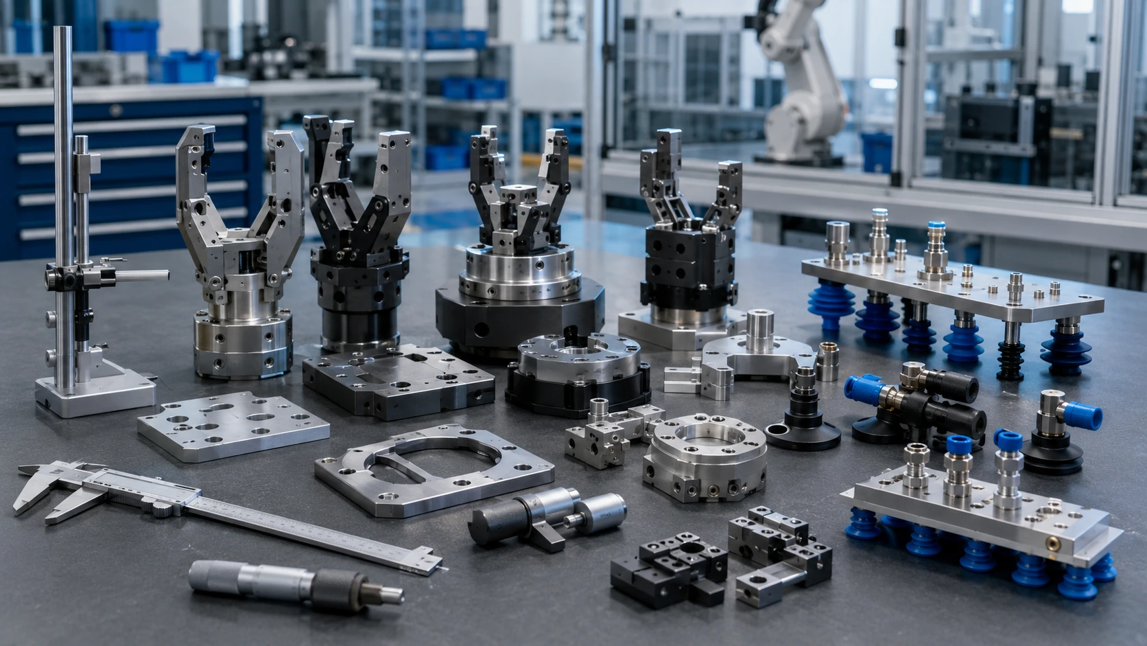
Custom robot end effectors are usually made from several groups of machined parts rather than one single component.
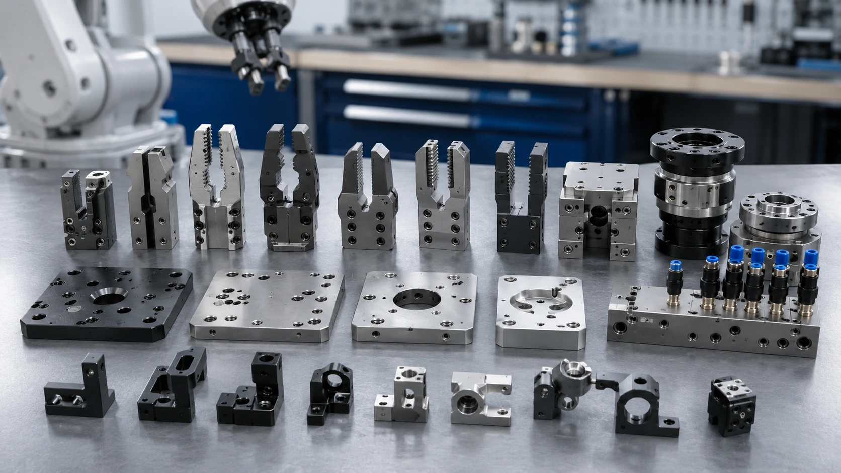
The first group is the contact hardware. CNC machined gripper fingers, robotic gripper fingers, custom gripper jaws, soft jaws, locating nests, V-block inserts, contoured supports, and replaceable contact pads directly touch the workpiece. Their geometry controls grip stability, part orientation, and marking risk.
The second group is structural EOAT hardware. Base plates, lightweight frames, robot wrist adapters, spacer blocks, alignment plates, bracket arms, and gripper mounting plates hold the gripper system together. These parts need stiffness, flatness, accurate hole patterns, and clean assembly surfaces.
Vacuum and pneumatic tooling forms another group. Vacuum end effector parts may include vacuum manifold plates, suction cup mounts, air channels, hose routing blocks, valve plates, and distribution blocks. These parts often need sealing faces, smooth channels, and careful deburring to avoid leaks or contamination.
Sensor integration is becoming more common. Camera brackets, proximity sensor mounts, force sensor adapters, vision alignment plates, protective housings, and cable clamps help the robot detect, confirm, and adjust the gripping process.
| Gripper / EOAT Part | Why CNC Machining Is Used | Common Material |
|---|---|---|
| Gripper finger | Accurate contact geometry | Aluminum, POM, steel |
| EOAT mounting plate | Flatness and hole position | Aluminum 6061 |
| Tool changer adapter | Repeatable robot interface | Aluminum 6061 / 7075 |
| Vacuum manifold | Air channels and sealing faces | Aluminum or POM |
| Sensor bracket | Stable alignment | Aluminum / stainless steel |
| Replaceable jaw insert | Wear control and part protection | POM, nylon, steel |
Material Selection for Robot Grippers and End Effectors
Material choice should start with the workpiece, not the machine.
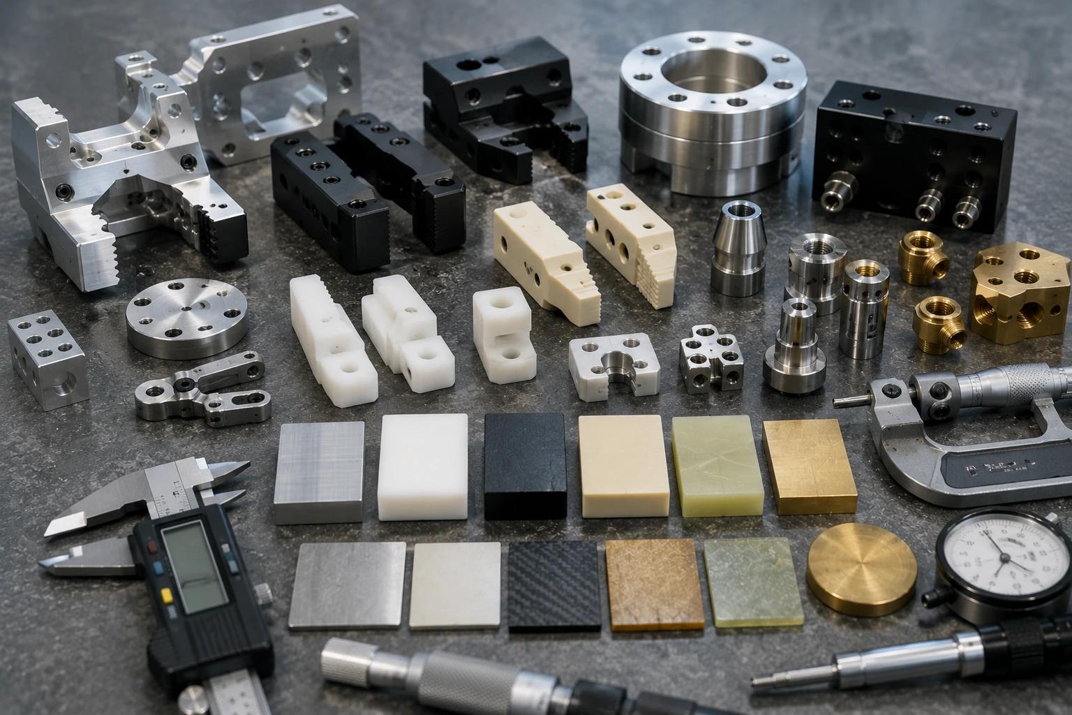
A gripper that handles rough castings does not need the same material as one handling polished plastic housings. A high-cycle machine tending jaw does not need the same surface as a vacuum tool for packaging. Precision robot gripping components depend on load, gripping force, cycle rate, contact pressure, marking risk, cleaning needs, temperature, and cost.
Aluminum 6061 is a strong general-purpose choice for EOAT plates, gripper bodies, brackets, adapters, and lightweight structures. It machines well, keeps weight low, accepts anodizing, and allows design changes during prototype and low-volume builds.
Aluminum 7075 makes sense when stiffness and strength matter more, especially for thin arms, compact adapters, or high-load gripper structures. It costs more, so it should solve a real strength or stiffness problem.
Stainless steel and tool steel fit high-wear jaws, pins, shafts, and contact parts exposed to abrasive or heavy workpieces. They add durability, but they also add weight.
POM/Delrin is often useful for non-marking fingers, locating nests, guides, and sliding contact features. PEEK may be selected for heat, wear, insulation, or chemical resistance. Nylon can work for lightweight replaceable inserts.
For early comparison, Boona CNC machining material options page helps buyers shortlist practical metals and plastics before RFQ.
Tolerance Planning for CNC Machined Gripper Fingers
Gripper tolerances should focus on the features that control grip.
That sounds simple, but many EOAT drawings either under-specify the contact areas or over-specify the entire part. Both create problems.
For machined robot gripper parts, the critical areas usually include jaw contact faces, jaw parallelism, dowel pin holes, tool changer interfaces, mounting hole position, locating nests, V-grooves, vacuum sealing faces, sensor alignment features, and pneumatic connection surfaces. These features decide whether the end effector grips, locates, seals, and releases consistently.
A gripper finger may need ±0.02 mm to ±0.05 mm on a locating surface, while a lightening pocket can use general tolerance. A vacuum plate may need flatness and surface finish control on the sealing face, while the outside profile can remain non-critical. A tool changer adapter may need true position control on the robot interface holes.
Over-tolerancing every feature increases machining and inspection cost without improving grip reliability. Under-tolerancing the contact features can cause slipping, marking, part tilt, or inconsistent loading.
A 2D drawing helps. It tells the supplier which surfaces actually control the grip and which areas simply clear weight, cables, hoses, or covers.
| Feature | Why It Matters | Tolerance Strategy |
|---|---|---|
| Jaw contact face | Controls grip stability | Control geometry and finish |
| Dowel pin hole | Repeatable assembly | Reamed hole if required |
| Tool changer pattern | Robot interface accuracy | True position control |
| Vacuum sealing face | Prevents leakage | Flatness and surface finish |
| Lightening pocket | Usually non-critical | General tolerance |
| Cable slot | Clearance feature | Avoid tight tolerance |
Surface Finish, Deburring, and Part Marking Control
Surface finish can decide whether the gripper holds the part — or damages it.
A rough contact face may improve friction, but it can also mark a cosmetic housing. A very smooth face may protect the product but reduce grip stability. A sharp corner can scratch the workpiece, tear packaging, or damage cables. A poor sealing surface can cause vacuum loss. This is why surface finish should be connected to the actual gripping task.
For aluminum EOAT structures, anodizing is common because it improves corrosion resistance and gives a clean technical finish. Black anodizing can reduce reflection near cameras or optical sensors. Hard anodizing may improve wear resistance, but it can change dimensions, so critical fits and contact features should be reviewed before finishing.
POM or nylon inserts can reduce marking on plastic, painted, or polished parts. Steel jaws may need polishing, black oxide, plating, or heat treatment depending on wear and environment. Stainless steel may need passivation. Vacuum faces may need smoother machining and careful sealing control.
Deburring is not optional. Product contact edges, cable slots, hose passages, air channels, sensor brackets, and operator-touch areas should be clean. Burrs can scratch parts, trap debris, damage hoses, or create assembly issues.
The key question is not “What finish looks good?” It is “Should this gripper grip harder, avoid marks, seal better, or last longer?”
Lightweight EOAT Design for Faster Robot Motion
End-effector weight affects robot performance immediately.
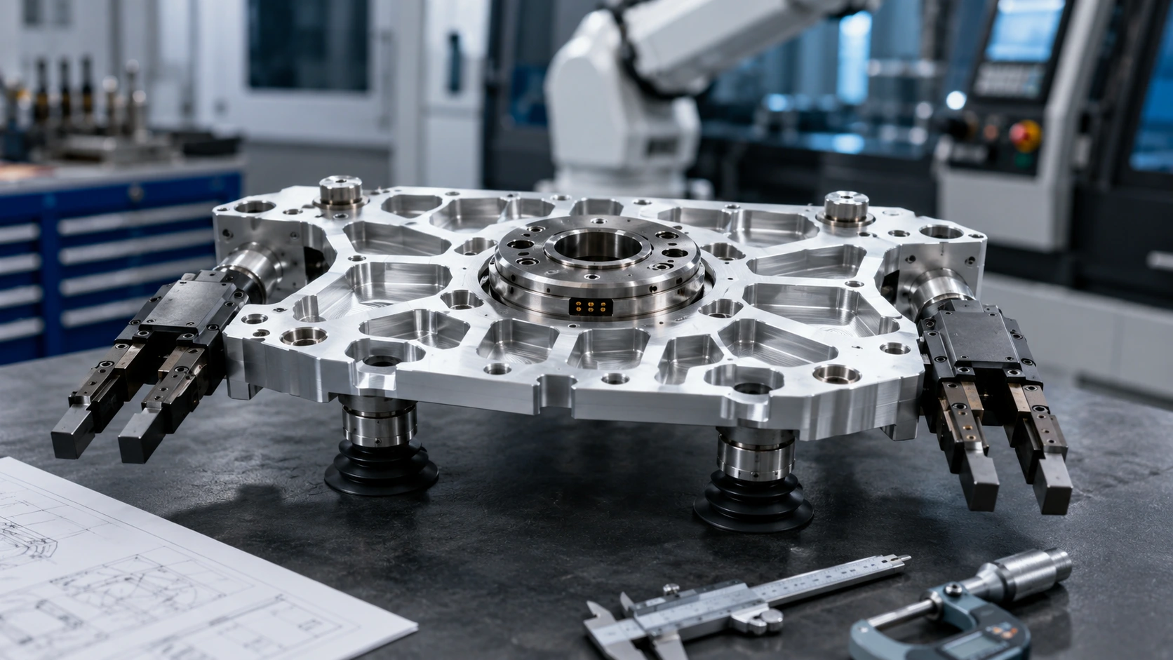
A heavier gripper reduces available payload. It can slow acceleration, increase braking load, extend cycle time, and reduce energy efficiency. On smaller collaborative robots, a few hundred grams may matter. On high-speed pick-and-place systems, end-effector weight can become the difference between a stable cycle and an unreliable one.
Lightweight EOAT design usually uses pocketed plates, ribbed brackets, hollow arms, aluminum instead of steel, plastic contact inserts, skeletonized structures, and optimized mounting plates. These are useful methods, but they need discipline.
Too much pocketing increases machining time. Thin plates can flex. Long gripper arms may lose stiffness. A lightweight bracket that bends under grip force is not an improvement. In my experience, many failed EOAT designs are not too heavy — they are light in the wrong places.
Keep stiffness near mounting points, dowel holes, tool changer interfaces, and contact surfaces. Remove material from low-stress areas. Use 7075 only when strength-to-weight justifies the cost. Choose POM inserts when the contact area needs lower weight and part protection.
| Design Choice | Benefit | Risk |
|---|---|---|
| Pocketed plate | Reduces weight | Adds machining time |
| Ribbed bracket | Keeps stiffness | Needs tool access |
| POM jaw insert | Reduces marking | Lower strength |
| Aluminum 7075 arm | High stiffness-to-weight ratio | Higher cost |
| Thin mounting plate | Saves mass | May flex |
| Hollow tooling arm | Large weight reduction | More setups |
CNC Machining vs 3D Printing for Robot Grippers
3D printing is useful for gripper development. It helps engineers test jaw shape, clearance, finger length, cable routing, sensor placement, and rough workpiece access quickly.
But robot end effector machining becomes the stronger choice when the EOAT needs production-like stiffness, threaded holes, vacuum sealing faces, accurate contact geometry, durable wear surfaces, and a reliable tool changer interface.
Printed jaws can answer the first question: “Does this shape reach the part?” CNC machined gripper fingers answer the next question: “Will this hold the part repeatedly without slipping, flexing, or marking?”
Many teams use both. They print two or three jaw concepts, test the grip path, then machine the functional version in aluminum, POM, steel, or a hybrid material stack. After testing, the jaw insert may be revised without changing the entire EOAT structure.
For early additive process selection, the related guide on MJF vs FDM 3D printing for functional prototype parts can help teams decide whether printed prototypes should be used only for form checks or for functional nylon testing.
CNC and 3D printing are not enemies. They answer different questions at different stages.
Application Example: Replacing a Printed Gripper With CNC Machined EOAT
A factory automation team needed a gripper for picking molded plastic housings from a tray and placing them into a test fixture. The first version used 3D printed jaws because the team wanted to check reach, clearance, and finger shape quickly.
That was the right first step.
After repeated testing, problems started to appear. The printed jaws wore at the contact area. One jaw started marking the plastic housing. The gripper body flexed slightly during faster motion, which changed how the part entered the fixture. The robot was not the issue. The gripper was.
The next version used a CNC machined aluminum EOAT plate with replaceable POM contact fingers. The aluminum plate improved stiffness and kept the robot interface stable. The POM inserts reduced marking on the housing. Dowel holes controlled finger location, and the contact faces were machined to match the part geometry more closely.
The result was not a flashy redesign. It was a better production tool: more stable grip, less marking, easier insert replacement, and more consistent part release.
💡 Pro Tip: Make wear surfaces replaceable whenever possible. A gripper body should not be scrapped because one contact edge wears out. Separate the structural EOAT plate from the replaceable finger or insert, especially for high-cycle automation.
Quality Control for CNC Machined End-Effector Parts
Quality inspection should follow grip function, not cosmetic appearance.
For custom EOAT components, the most important checks often include jaw contact geometry, jaw parallelism, mounting hole position, dowel pin holes, tool changer interface accuracy, vacuum sealing face flatness, threaded holes, and burrs on contact edges.
Calipers and micrometers handle many basic checks. Pin gauges and thread gauges confirm holes and threads. Height gauges help with parallelism and feature location. CMM inspection may be needed for robot wrist adapters, tool changer plates, high-accuracy gripper jaws, or pilot-batch EOAT parts. Surface roughness testing may be needed for sealing faces, sliding surfaces, or contact areas that must avoid marking.
Inspection should also include visual checks. Burrs, sharp edges, blocked air channels, rough contact areas, and damaged inserts can create problems even when dimensions pass.
NIST’s robotics work emphasizes performance metrics, test methods, and protocols for robotic systems. That idea applies to EOAT hardware as well: the gripper should not only fit the robot; it should perform predictably across cycles, workpieces, and maintenance events.
Good inspection reduces slipping, marking, vacuum leakage, assembly errors, and inconsistent gripping.
Cost Drivers and DFM Tips for Robot Gripper Machining
The cost of gripper and EOAT machining usually comes from geometry, tolerance, material, finish, and quantity — not just part size.
Complex jaw contours increase machining time. Deep pockets require longer tools. Thin arms need careful workholding. Stainless steel jaws cost more to machine than aluminum or POM. Tight tolerance everywhere adds inspection time. Hard anodizing, polishing, plating, or special masking can add lead time. Low quantities spread setup cost over fewer parts.
Good DFM makes grippers easier to machine, assemble, and maintain. Use replaceable jaw inserts. Add tool-friendly internal radii. Keep enough material around threaded holes and dowel locations. Avoid deep narrow pockets unless they reduce meaningful weight. Leave access for sensors, hoses, and fasteners. Define the real contact surfaces clearly. Separate wear parts from structural parts.
Vacuum tooling needs extra care. Avoid hidden burr traps in air channels. Give sealing faces enough flat area. Make hose routing serviceable. Keep suction cup mounting points accessible.
| Cost Driver | Why It Raises Cost | Buyer Tip |
|---|---|---|
| Complex jaw contour | Longer machining time | Use only where needed |
| Tight tolerance everywhere | More machining and inspection | Control contact and mounting areas only |
| Stainless steel jaws | More tool wear and time | Use only for wear or strength |
| Deep pockets | Longer tool time | Add radii and improve access |
| Hard anodizing | Finish control required | Protect critical fits |
| Low quantity | Higher setup cost per part | Batch similar parts |
RFQ Checklist for Robot Grippers and End Effectors
A CAD file shows shape. It does not explain the grip.
For robot gripper and EOAT RFQs, buyers should send the 3D CAD file, 2D drawing, robot model or tool interface, gripper type, workpiece material, workpiece weight, contact surface requirement, gripping force if known, cycle rate, quantity, material preference, surface finish, critical tolerances, vacuum or pneumatic details, sensor mounting needs, inspection report requirements, and lead time.
A short function note helps suppliers quote more accurately:
“CNC machined aluminum EOAT plate with POM gripper fingers, 12 sets, for pick-and-place plastic housing, non-marking contact surface required, dowel holes and tool changer interface critical.”
Now the supplier understands the function. It is not just a plate and two jaws. It is a repeatable gripping system with contact, marking, alignment, and interface requirements.
If the part is for testing only, say so. If it will run production cycles, mention the cycle rate. If marking is unacceptable, define the surface requirement. If wear inserts should be replaceable, include that before machining.
Clear RFQs reduce assumptions. They also reduce rework.
Related Reading
For broader robot hardware planning, read our guide to CNC machining for robotics. If your team is sourcing mechanical parts for AI-enabled systems, the article on custom CNC machined parts for AI robots gives useful buyer-side context. For humanoid platforms with compact joints and actuator housings, review our guide to humanoid robot parts machining.
Conclusion: CNC Machining for Robot Grippers Needs Function-First Design
CNC machining for robot grippers helps automation teams build end effectors that grip, locate, release, and repeat reliably.
A good gripper starts with the workpiece. Choose materials based on load, wear, weight, contact pressure, and marking risk. Control tolerance where grip function depends on it: contact faces, dowel holes, tool changer interfaces, vacuum sealing surfaces, and sensor mounts. Use surface finish to manage friction, wear, sealing, cleaning, and product protection. Keep EOAT structures light, but not flexible. Make wear surfaces replaceable whenever possible.
For prototype and low-volume automation tooling, CNC machining gives engineers real materials, accurate interfaces, and room to revise designs after testing.
If you are developing robot gripper fingers, EOAT plates, tool changer adapters, vacuum manifold parts, or other custom end-effector components, send your CAD files, workpiece details, drawings, and gripping requirements to Boona custom CNC machining team. We can help review materials, tolerances, DFM, finishing, and inspection needs before machining starts.
FAQs
What robot gripper parts are commonly CNC machined?
CNC machined robot gripper parts include gripper fingers, custom jaws, soft jaws, EOAT plates, tool changer adapters, vacuum manifolds, suction cup mounts, sensor brackets, and replaceable contact inserts. These parts control how the robot holds, locates, moves, and releases the workpiece.
Why is CNC machining used for robot grippers?
CNC machining is used for robot grippers because it provides accurate contact geometry, repeatable mounting holes, stable EOAT structures, threaded features, and reliable material strength. It is useful when the gripper must survive repeated cycles, hold tolerance, avoid part marking, or interface accurately with the robot wrist.
What material is best for CNC machined gripper fingers?
The best material depends on the workpiece and gripping conditions. Aluminum works well for structural gripper fingers, POM is useful for non-marking contact, stainless steel suits high-wear jaws, and PEEK may be used for heat, chemical resistance, or insulation requirements.
Is CNC machining better than 3D printing for robot end effectors?
CNC machining is better for production-like EOAT parts, high-wear jaws, vacuum sealing faces, tool changer adapters, and precision gripper fingers. 3D printing is useful for early shape checks, jaw concept models, cable routing tests, and temporary low-load prototypes.
What tolerances matter for robot grippers?
Critical tolerances for robot grippers usually include jaw contact geometry, jaw parallelism, dowel pin holes, mounting hole position, tool changer interfaces, vacuum sealing faces, and sensor alignment features. Non-critical lightening pockets and clearance areas can often use general tolerances.
How can buyers reduce robot gripper machining cost?
Buyers can reduce cost by using standard materials, avoiding unnecessary tight tolerances, simplifying jaw contours, making wear inserts replaceable, using standard fasteners, batching similar parts, and sending clear drawings. Good DFM should reduce cost without weakening the gripper.