
“Make it from copper because copper conducts heat better” sounds like a complete material decision. It rarely is. Machining Aluminum and Copper Heat Sinks begins with a wider question: how will heat move through the base, interface, fins, and airflow path?
Choosing copper too early can add weight, machining difficulty, material cost, and mounting loads. Selecting aluminum solely to reduce cost can leave a concentrated heat source with inadequate spreading. Either material can underperform if the base bows after machining, burrs restrict narrow channels, or a coating covers the thermal interface.
A reliable decision connects material properties with geometry, airflow, mounting pressure, manufacturing sequence, finishing, and verification.
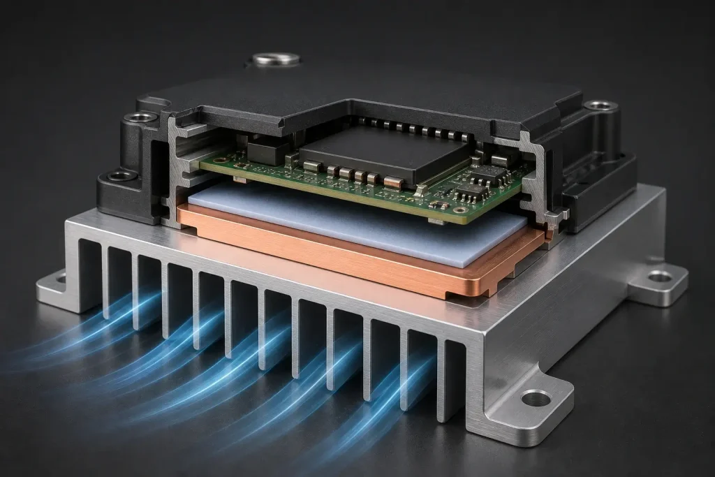
How a Machined Heat Sink Controls Component Temperature
A heat sink transfers energy through several connected stages. Heat leaves the semiconductor package, crosses the thermal interface material, spreads through the base, travels into the fins, and enters the surrounding air or coolant.
Engineers commonly express this performance as thermal resistance:
Rθ = (Tsource − Tambient) / Q
Here, Rθ is thermal resistance in °C/W, Tsource is the component or interface temperature, Tambient is the local ambient temperature, and Q is dissipated power in watts. Lower thermal resistance generally supports a lower component temperature under the same operating load.
Bulk conductivity affects spreading resistance, particularly where a small semiconductor package delivers heat into a much larger sink. Base thickness, contact pressure, interface-material thickness, fin area, channel geometry, airflow direction, and surface flatness also influence the final temperature.
Before choosing a metal, define the heat load, acceptable component temperature, ambient range, available airflow, heat-source footprint, mounting envelope, orientation, shock or vibration loads, and weight limit. These inputs establish whether the project needs a complete aluminum sink, a compact copper spreader, or a hybrid structure.
Choosing Materials for Machining Aluminum and Copper Heat Sinks
Aluminum remains a practical choice for power supplies, LED modules, communication devices, industrial controls, and embedded computers. It combines useful conductivity with low density, corrosion resistance, and predictable machining.
The Aluminum Association’s December 2025 alloy designation data lists nominal densities of 2.70 g/cm³ for both 6061 and 6063. A peer-reviewed 2022 experiment on machined microchannel heat sinks used 6063 aluminum with a thermal conductivity of 204 W/m·K at 25°C. Material properties vary with alloy, temper, temperature, and product form, so production drawings should identify the required grade and condition.
Copper provides stronger spreading where high heat flux enters a small footprint. An Aurubis Cu-ETP data sheet issued in January 2026 lists thermal conductivity of 390 W/m·K in the soft condition and density of 8.9 g/cm³. The same volume of copper therefore weighs approximately 3.3 times as much as aluminum.
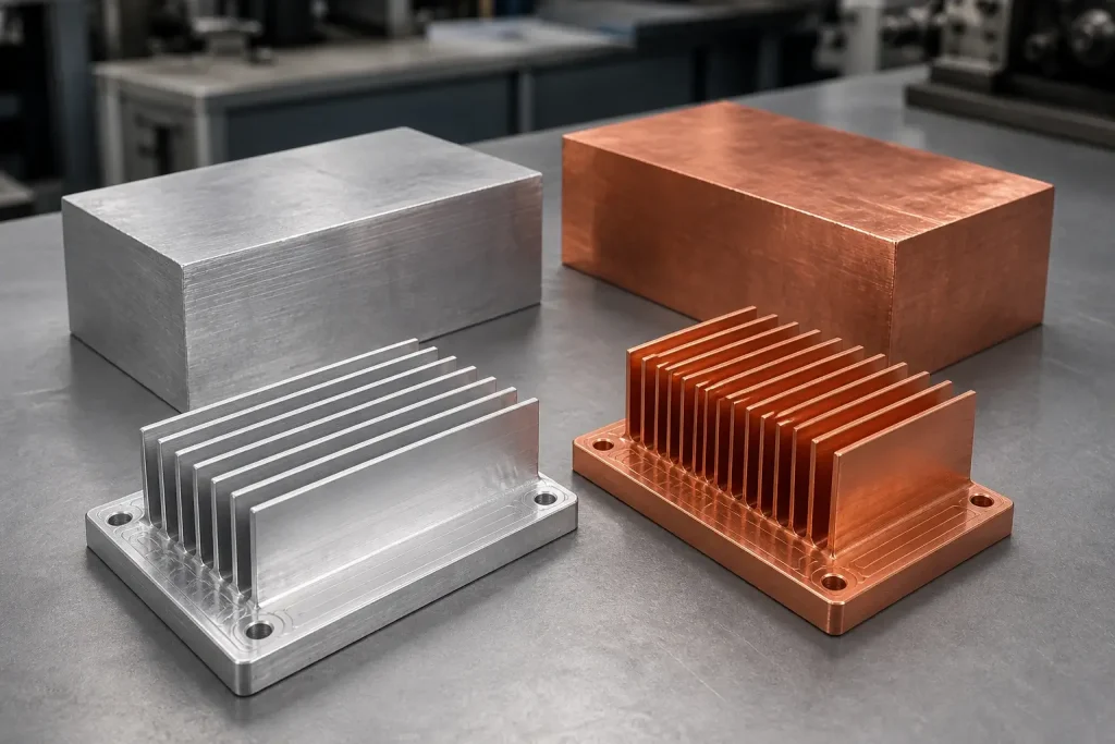
| Decision factor | Aluminum 6061 or 6063 | C110 copper or Cu-ETP |
|---|---|---|
| Representative density | About 2.70 g/cm³ | About 8.9 g/cm³ |
| Representative conductivity | 204 W/m·K for the study’s 6063 material | 390 W/m·K in the cited soft condition |
| Heat-spreading capability | Suitable for many moderate-load systems | Strong for concentrated heat sources |
| Machining behavior | Generally predictable with suitable tooling | Ductile chips and burrs require close control |
| Weight impact | Favors mobile and airborne equipment | Requires mounting and structural review |
| Common role | Complete base-and-fin heat sink | Spreader, insert, cold plate, or compact sink |
| Typical finish route | Anodizing or conversion coating | Bare, anti-tarnish treated, or plated |
When CNC Machining Is the Right Heat-Sink Process
Several manufacturing processes can produce heat sinks. Extrusion suits constant cross-sections and stable production volumes. Skiving creates dense straight fins. Bonded-fin construction supports large assemblies, while die casting can consolidate features when volume justifies tooling.
CNC machined heat sinks become valuable when thermal features must share datums with precise mechanical interfaces. Machining can integrate localized fin fields, threaded holes, O-ring grooves, connector reliefs, sensor pockets, component clearances, fluid ports, and mounting surfaces into one component.
This flexibility suits prototypes, pilot production, custom industrial electronics, optical equipment, robotics, aerospace systems, and power modules with irregular envelopes. Engineers can also revise a machined design without committing to new extrusion or casting tooling.
Machining becomes less economical when a part requires very tall, densely spaced fins across a large area. Long tools increase deflection, cycle time, and chip-removal difficulty. Large amounts of removed stock add material cost. Compare the proposed design with extrusion, skiving, brazed fins, heat pipes, vapor chambers, and hybrid copper-aluminum construction before locking the process.
Process Challenges in Machining Aluminum and Copper Heat Sinks
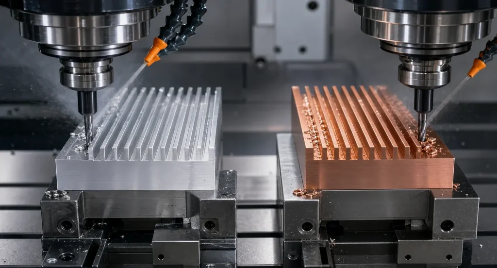
Aluminum heat sink machining
Thin aluminum fins can vibrate or bend as the cutter removes surrounding support. Long-reach tools magnify runout and deflection, while chips trapped in deep channels can scratch walls or damage fin edges.
A stable process often leaves supporting material around delicate features until later operations. Sharp tools, appropriate flute geometry, controlled engagement, balanced stock removal, and effective chip evacuation help preserve the base and fins. Designs with significant stock removal may require roughing, semi-finishing, and final machining from stable datums.
Programs that combine thermal features with housings, mounting interfaces, or angled passages can use BOONA aluminum CNC machining service to review tool access, workholding, and datum strategy.
Copper heat sink machining
Copper’s ductility encourages long chips, built-up edge, smeared surfaces, and burrs along thin walls. Excessive rubbing generates heat and can distort delicate fins. Sharp cutting edges and deliberate chip control therefore matter throughout copper heat sink machining.
Soft copper surfaces also mark easily under clamps and during handling. A process for custom copper CNC machining should define clamping locations, protective handling, deburring access, interface-surface requirements, and final plating or anti-tarnish treatment before machining begins.
DFM Rules for Machining Aluminum and Copper Heat Sinks
Effective heat sink fin design balances surface area, airflow resistance, weight, and machinability. Adding more fins reduces the open flow area and may increase pressure drop. Narrow slots also require smaller or longer cutters, raising the risk of deflection and chip packing.
Review these features during DFM:
- Match channel width to an accessible cutter diameter and chip-clearance path.
- Set fin height and thickness according to material, tool reach, and surface requirements.
- Include internal corner radii that reflect the selected end mill.
- Keep threaded holes and mounting bosses from weakening the thermal base.
- Use the component-contact surface as a functional datum where appropriate.
- Apply flatness to the actual heat-source contact area.
- Provide clearance for fasteners, washers, connectors, and assembly tools.
- Identify coating-free thermal and electrical contact areas on the drawing.
- Avoid unnecessary tolerances on fins that only increase surface area.
A thicker base can improve spreading and stiffness, but it adds weight and thermal mass. A thinner base responds quickly and reduces material, yet it may bow during machining or screw tightening. Thermal and structural evaluation should include the actual source footprint, interface layer, fastener pattern, and mounting support.
Pro Tip: Release the CAD model with a controlled drawing that identifies the thermal-contact area, primary datum, flatness requirement, coating masks, assembly torque, and cosmetic zones. Geometry alone cannot communicate the complete thermal requirement.
Surface Finishing and Interface Management
Surface treatment should follow the assembly’s environmental, electrical, cosmetic, and thermal requirements.
Anodizing can improve corrosion and wear resistance on aluminum while providing a consistent appearance. Because the oxide layer is electrically insulating, grounding points, threaded interfaces, and direct-contact zones may need masking. Coating buildup also affects close fits and small holes.
Chemical conversion coatings can support corrosion protection and electrical bonding, depending on the chosen process and specification. Copper may remain bare, receive an anti-tarnish treatment, or use nickel or another specified plating system. Plating decisions should consider corrosion exposure, solderability, electrical contact, thermal cycling, and dimensional allowance.
The heat-source interface needs separate control. A reflective surface does not guarantee low contact resistance. Flatness, waviness, roughness, cleanliness, interface-material thickness, and clamp pressure work together.
Extremely fine finishes can raise machining cost without improving a joint that uses a relatively thick thermal pad. Deep cutter marks, raised burrs, and local high points can prevent full seating even when overall dimensions pass inspection.
Inspection and Thermal Verification
Inspection should concentrate on characteristics that affect heat transfer, airflow, sealing, and assembly. These commonly include base flatness, fin thickness, channel width, overall height, mounting-hole position, thread quality, sealing grooves, and connector clearances.
A coordinate measuring machine can verify datums and mounting features. Optical measurement may suit dense fins that a touch probe cannot access. A profilometer can characterize the component-contact surface. Flatness inspection should follow the drawing’s specified free-state or restrained-state condition because clamping can temporarily conceal distortion.
The previously cited 2022 copper and aluminum microchannel study examined 36 channels measuring 0.46 × 0.46 mm, separated by 0.10 mm walls. At wall heat fluxes up to 174 kW/m², the aluminum sink averaged a 12% higher heat-transfer coefficient and a 28% higher pressure drop. Overall thermal performance remained similar between the two materials.
The researchers connected part of this difference to machining-created surface cavities and fluid behavior. This specialized flow-boiling experiment cannot establish a universal material ranking. It does show why validation must use the finished channel geometry, surface condition, coolant, flow rate, mounting state, and operating range.
Application Example: A CNC-Machined CubeSat Battery Heat Sink
A 2026 Energies study of CubeSat battery thermal management illustrates how material and machined geometry can support the same thermal strategy.
Researchers fabricated sealed aluminum heat-sink enclosures with an approximately 4 × 4-inch cross-section to match Pumpkin and OPTIMUS CubeSat battery modules. They CNC-machined three equal-height legs directly into each lid. These legs pressed thermal-conductivity-enhancing foam against the bottom wall to maintain a direct heat path.
The experiment applied a 10 W heat input and used paraffin phase-change material that melted near 37°C. Researchers compared baseline PCM with composites incorporating carbon foam, expanded graphite, and open-cell copper foam under atmospheric and vacuum conditions. The copper-foam and carbon-foam configurations operated approximately 4°C cooler than the baseline and reduced overall thermal resistance by as much as 40%.
This was a published laboratory study, rather than a BOONA customer project or confirmed flown system. The paper does not publish the aluminum alloy, machining tolerances, GD&T, surface finish, or lid-flatness specification.
Manufacturing implications can still be inferred from the design. Consistent leg height controls foam compression, the lower wall supports repeatable thermal contact, and the gasket groove and fastener pattern preserve the sealed enclosure. These observations are engineering inferences from the published architecture.
What to Include in a Heat-Sink RFQ
A complete RFQ allows the manufacturing team to evaluate thermal intent alongside machining risk. Include:
- Native 3D CAD and a controlled 2D drawing
- Material grade, temper, and approved alternatives
- Prototype and expected production quantities
- Heat-source footprint and dissipated power
- Maximum component or interface temperature
- Ambient temperature and airflow or coolant conditions
- Thermal interface material and compressed thickness
- Mounting pattern, fastener type, and assembly torque
- Critical datums, flatness, position, and surface-finish requirements
- Electrical bonding or isolation requirements
- Surface treatment and masking zones
- Burr, cleanliness, and cosmetic acceptance criteria
- Inspection-report and thermal-test expectations
State whether the supplied part represents a complete heat sink, a spreader, a cold plate, or one element of a larger enclosure. If the assembly later receives copper inserts, heat pipes, bonded fins, or brazed components, include that process sequence as well.
FAQs
Is copper always better than aluminum for a heat sink?
Copper spreads concentrated heat effectively, while aluminum reduces mass and supports efficient machining. System performance also depends on geometry, airflow, interface resistance, mounting pressure, and available space.
Which aluminum grade is suitable for a machined heat sink?
6061-T6 is commonly selected where the heat sink also needs structural strength, threaded features, and predictable machining. 6063 offers useful thermal properties and often appears in extruded heat sinks. Final selection should reflect stock form, mechanical loading, finishing, and the verified thermal model.
How thin can CNC-machined heat-sink fins be?
No universal minimum applies. Material, fin height, slot width, cutter diameter, tool reach, machine stability, quantity, and surface requirements all affect feasibility. Thin, tall fins require more conservative machining than short, widely spaced fins.
Does anodizing affect heat-sink performance?
Anodizing changes the aluminum surface and creates an electrically insulating layer. Its effect depends on the thermal path. Direct component-contact areas, grounding points, and tight fits may require masking.
How flat should a heat-sink base be?
Flatness should match the heat-source footprint, thermal interface material, mounting pattern, and clamp pressure. An unnecessarily tight requirement raises manufacturing cost, while inadequate control can produce gaps and increased contact resistance.
Can aluminum and copper be combined in one heat sink?
Yes. A copper spreader can collect heat from a concentrated source while an aluminum fin structure controls mass. The design must address joining, galvanic compatibility, thermal expansion, interface resistance, and inspection access.
Conclusion
Machining Aluminum and Copper Heat Sinks succeeds when the material, geometry, interface, manufacturing process, and test method support the same thermal objective.
Aluminum offers a strong balance of weight, machinability, corrosion resistance, and heat transfer. Copper provides higher conductivity for concentrated loads, along with additional mass and more demanding chip and burr control. Hybrid designs can place each metal where it contributes the greatest system-level benefit.
Before production, define the heat load, airflow, mounting condition, base flatness, fin geometry, coating masks, and inspection state. Validate the finished part under representative operating conditions rather than relying on conductivity alone.
If your heat sink combines narrow channels, thin fins, critical interface flatness, copper spreaders, or integrated mounting features, send BOONA the CAD model, drawing, material specification, and thermal requirements. The team can review manufacturing risks through its precision CNC machining services before production.


