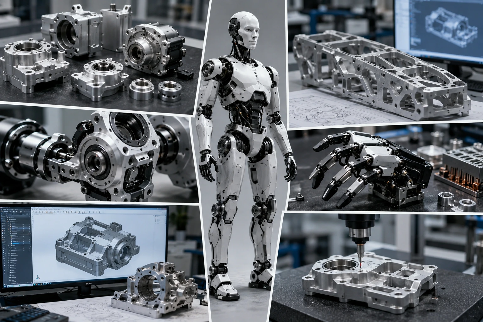
A humanoid robot can look impressive in a demo and still fail during real mechanical testing.
The AI model works. The vision system recognizes objects. The motion plan looks smooth in simulation. Then the robot starts walking, lifting, turning, or gripping — and the weak point becomes obvious. A knee joint has play. An actuator housing runs hot. A shoulder frame flexes. A sensor bracket vibrates enough to affect calibration.
That is where humanoid robot parts become more than mechanical details.
Humanoid robots pack motors, reducers, bearings, encoders, sensors, cables, batteries, control boards, and structural frames into very limited space. Every gram matters. So does every bearing bore, dowel hole, motor face, threaded feature, and joint interface.
For robotics startups, OEM engineers, sourcing teams, and product developers, CNC machining is often the most practical way to produce actuator housings, robot joints, lightweight frames, sensor mounts, gripper parts, and validation hardware before higher-volume tooling makes sense.
Why Humanoid Robot Parts Need Precision Machining
Humanoid robot parts face a harder mechanical job than many standard automation components. A fixed robot arm can rely on a rigid base and a controlled work cell. A humanoid robot has to balance, recover, carry load, move through space, and keep sensors aligned while its own structure keeps shifting.
That changes the manufacturing requirement.
Actuator alignment affects motion control. Bearing bores affect joint smoothness. Frame stiffness affects balance and gait stability. Sensor mounts affect perception. Heat sinks and motor covers affect long-duration testing. If one mechanical interface shifts, the control software may compensate for a while, but the robot still loses repeatability.
The robotics market is moving quickly. The International Federation of Robotics reported 4,281,585 industrial robots operating worldwide in 2023, and annual installations reached 541,302 units. The same report shows industrial robots are still expanding across manufacturing regions, which helps explain why more buyers now care about reliable robot hardware, not only software.
For prototypes and pilot builds, precision CNC machining services give engineers real materials, threaded holes, accurate fits, and repeatable parts without waiting for die casting, molding, or other tooling.
Common CNC Machined Humanoid Robot Parts
CNC machined humanoid robot parts usually fall into several practical groups.
The first group is the drive system. Actuator housings, motor shells, harmonic drive housings, gearbox covers, bearing seats, shaft couplers, encoder brackets, pulley mounts, and motor heat covers all control alignment, torque transfer, and service access. These parts often look like compact aluminum blocks, but they carry a lot of responsibility.
Joint components come next. Shoulder, elbow, wrist, hip, knee, and ankle joints need accurate side plates, bearing carriers, rotary housings, reducer mounts, and mating faces. A small machining error here can create backlash, vibration, uneven loading, or early bearing wear.
Frame parts carry the robot’s structure while trying not to add too much weight. Torso frames, hip frames, leg structures, arm links, support ribs, and mounting plates often use pocketed aluminum designs. They need stiffness, but not unnecessary mass.
Sensor and electronics parts also deserve attention. Camera mounts, depth sensor housings, IMU blocks, electronics enclosures, cable routing blocks, heat sinks, and heat spreaders may look secondary, but they affect perception, thermal control, and assembly reliability.
For buyers comparing humanoid hardware with broader robot sourcing needs, our guide to custom CNC machined parts for AI robots gives more context on materials, tolerances, surface finishes, and RFQ planning.
| Humanoid Robot Part | Why CNC Machining Is Used | Common Material |
|---|---|---|
| Actuator housing | Bearing, motor, and gearbox alignment | Aluminum 6061 / 7075 |
| Joint side plate | Strength and repeatable motion | Aluminum 7075 |
| Torso frame | Lightweight structural support | Aluminum 6061 / 7075 |
| Sensor mount | Stable vision and perception alignment | Aluminum / stainless steel |
| Gripper part | Contact geometry and wear resistance | Aluminum / POM / steel |
| Heat sink | Thermal control for motors or electronics | Aluminum / copper |
Machining Humanoid Robot Actuator Housings
A humanoid robot actuator housing is not just a protective shell. It is the reference structure for the motor, reducer, bearing system, encoder, cable path, and often the thermal path.
That is why these parts need careful machining. Bearing bores must hold the right fit. Motor mounting faces need flatness. Dowel pin holes may need reaming for repeatable assembly. Threaded holes need enough engagement for repeated service. Cable slots need smooth edges. Cooling fins or heat-transfer walls need enough material and tool access.
Poor machining creates problems that appear later. A loose bearing fit can create joint play. Poor concentricity can add vibration. A motor face that is not flat may affect gearbox alignment. Sharp cable exits can damage wires during assembly. A wall that is too thin may save weight but lose stiffness.
Compact actuator housings often need features on several sides. For simple housings, 3-axis machining may be enough. For complex actuator bodies with angled faces, side features, pockets, and tight access, 5-axis CNC machining for complex robot housings can reduce refixturing and improve feature access.
| Feature | Function | Machining Note |
|---|---|---|
| Bearing bore | Supports smooth rotation | Tight fit tolerance required |
| Motor mounting face | Controls alignment | Flatness and position matter |
| Dowel pin hole | Repeatable assembly | Reaming may be needed |
| Cable slot | Wire routing | Edge break required |
| Cooling fins | Heat control | Tool access affects cost |
| Threaded holes | Assembly fastening | Use standard threads where possible |
Robot Joint Machining for Smooth Motion
Robot joint machining directly affects how a humanoid robot moves. That sounds obvious, but it is easy to underestimate when the part still looks good on the bench.
Humanoid joints see repeated motion, load changes, vibration, and impact from walking or manipulation. Knee and ankle joints carry high dynamic loads. Shoulder and wrist joints often need compact packaging with a wide range of motion. Hip joints must handle load transfer, balance, and multi-axis movement.
The machining details matter. Bearing seats, shaft holes, reducer interfaces, mating faces, joint side plates, dowel holes, and mounting patterns all influence smoothness and service life. Concentricity, perpendicularity, flatness, true position, and runout often matter more than a simple outside profile tolerance.
Material choice also depends on the joint. Aluminum 7075 may fit lightweight, high-strength joint plates. Aluminum 6061 works for many general housings. Stainless steel is better for pins, shafts, and wear features. POM or PEEK may work for low-friction, insulating, or wear-related parts where metal is not ideal.
A joint can assemble correctly and still perform badly after cycling. That is why 2D drawings, GD&T, and inspection reports become more important as the project moves from prototype to validation.
Robot Frame Machining for Lightweight Structure
Robot frame machining is a balance between mass, stiffness, cost, and machinability.
Humanoid robots are sensitive to weight. A heavier arm requires more actuator torque. A heavier torso affects balance. A heavier leg increases energy use and can make walking control harder. At the same time, weak frames cause flex, vibration, and poor repeatability.
Engineers often use pocketing, ribs, hollow structures, thin-wall sections, and high-strength aluminum to reduce weight. These methods can work, but each one adds manufacturing trade-offs. Deep pockets increase machining time. Thin walls may chatter during cutting. Small internal radii require small tools. Aggressive hollowing can weaken the load path around bearings, screws, dowel holes, or joint interfaces.
Good lightweight design removes material from low-stress areas while protecting functional zones. Keep material around bearing bores. Leave enough thread engagement. Use internal radii that real cutters can machine. Avoid deep narrow pockets unless the weight saving justifies the extra cycle time.
My view is simple: do not chase lightweight design before the mechanism is stable. First make the humanoid robot move reliably. Then remove weight with intent.
Material Selection for Precision Humanoid Robot Components
Precision humanoid robot components should be material-selected by function, not by habit.
Aluminum 6061 is the practical starting point for housings, brackets, plates, sensor mounts, prototypes, and many frame parts. It machines well, keeps weight low, accepts anodizing, and keeps cost under control. Aluminum 7075 enters when strength-to-weight becomes more serious, especially for high-load joint plates, lightweight arm links, and frame members.
7075-T6 aluminum is commonly listed with about 572 MPa ultimate tensile strength and 2.81 g/cm³ density. That explains why engineers consider it for stressed lightweight structures, but it should not be applied everywhere by default. Cost, corrosion protection, finish, and actual load path still matter.
Stainless steel fits pins, shafts, wear parts, fasteners, and small high-load features. It adds weight, but it handles contact and corrosion well. POM/Delrin works for low-friction guides and gripper parts. PEEK supports heat resistance, wear resistance, insulation, and chemical stability. Nylon can reduce weight in less critical wear parts.
Copper and brass serve specific roles. Copper helps with heat sinks, heat spreaders, and electrical conductivity. Brass can work for bushings, fittings, or smaller electrical components. Boona CNC machining material options page can help buyers shortlist practical metals and plastics.
Tolerance and GD&T Planning for Humanoid Robot Parts
Custom humanoid robot parts need accuracy, but not every surface needs extreme tolerance.
Critical interfaces deserve control. Bearing bores, motor mounting faces, gearbox interfaces, dowel pin holes, joint mating faces, shaft holes, encoder locations, and sensor alignment surfaces often need tighter tolerances. Depending on function, buyers may call out ±0.02 mm to ±0.05 mm on selected features, H7-style bearing fits, reamed dowel holes, or GD&T controls for true position, flatness, perpendicularity, concentricity, parallelism, and runout.
Non-critical pockets, covers, cable clearances, cosmetic profiles, and lightening cutouts can usually follow general tolerances. Making everything tight does not automatically make the robot better. It does make machining, inspection, and quoting slower.
A 3D model shows shape, but it does not show design intent. For any humanoid robot part with critical interfaces, send a 2D drawing. Mark what matters. Leave clearance where the function allows it. If the supplier understands the joint, actuator, or frame function, they can help avoid unnecessary cost without weakening the design.
NIST’s robotics work emphasizes performance metrics, test methods, information models, and protocols for robotic systems. That same mindset applies to machined hardware: parts should behave predictably under motion, load, assembly, and service conditions.
Surface Finishing and Deburring for Humanoid Robot Parts
Surface finishing is functional in humanoid robots. It is not only about appearance.
Anodizing is common for aluminum parts because it improves corrosion resistance, gives a clean technical look, and supports color coding during prototype builds. Black anodizing is useful near cameras and optical sensors because it reduces reflection. Hard anodizing can improve wear resistance, but it can also change dimensions, so critical bores and sliding fits should be reviewed before finishing.
Bead blasting can create a uniform matte appearance before anodizing. Stainless steel may need passivation. Steel parts may use black oxide or nickel plating. Copper heat spreaders may need controlled surface roughness where they contact thermal pads or electronics.
Deburring deserves extra attention. Humanoid robots contain compact wiring, belts, seals, fasteners, sensor cables, and hand-contact areas. A sharp edge near a cable channel can damage insulation. A burr in a threaded hole can slow assembly. A sharp gripper edge can mark the object being handled.
Where sliding, sealing, bearing contact, or thermal contact matters, surface roughness should be specified. Where it does not matter, avoid over-specifying finish. Boona surface finishing guidance for machined parts can help compare anodizing, bead blasting, polishing, plating, and deburring options.
CNC Machining vs 3D Printing for Humanoid Robot Prototype Parts
Humanoid robot prototype parts often start with 3D printing. That is usually the right move.
Printed covers, cable routing mockups, ergonomic shells, non-load brackets, and quick assembly models help teams learn fast. The problem starts when printed parts are asked to behave like machined hardware.
Actuator housings, joint side plates, bearing seats, motor mounts, heat sinks, and structural frame components need stiffness, threaded strength, bearing fit, surface finish, and real material behavior. CNC machining is usually the stronger choice for these functional parts. Printed parts confirm shape. Machined parts test performance.
A staged development path often works best. Use 3D printing for early form checks. Use CNC machining for functional prototypes. Then machine pilot batches once the design stabilizes. For projects that compare additive options before machining, the related guide on MJF vs FDM 3D printing for functional prototype parts gives useful process-selection context.
This does not mean 3D printing is inferior. It means each process should be used for the right question: form, function, or final material behavior.
Low-Volume Humanoid Robot Parts and Pilot Builds
Low-volume humanoid robot parts are common because humanoid robot designs change often before production stabilizes.
An actuator size changes. A gearbox supplier changes. Cable routing needs more space. A knee joint needs more stiffness. A wrist cover needs service access. A sensor moves after calibration testing. These changes are normal when teams move from bench prototype to walking test, field demo, or pilot customer build.
CNC machining supports this development style because it does not require mold tooling. A team can machine 5 parts, test them, revise the CAD model, and machine 20 more. For humanoid robots, that flexibility is valuable because the mechanical layout often changes after real motion testing.
Quantities may stay low for a long time: 5 pieces for a first prototype, 10–20 for validation, 50–100 for pilot builds, and small batches for early customer units. At these volumes, machining often makes more sense than die casting, injection molding, or stamping.
Once the design becomes stable, other processes may reduce unit cost. Until then, CNC machining keeps engineering control close to the design team.
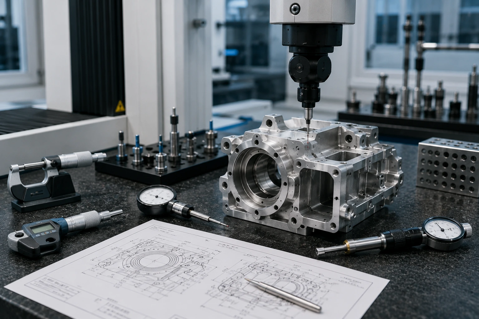
Quality Control for Machined Humanoid Robot Parts
Inspection should match the risk of the humanoid robot part.
A cosmetic cover does not need the same inspection plan as an actuator housing. A cable guide does not need the same report as a knee joint side plate. Treating every feature as critical wastes money. Treating critical interfaces casually creates bigger problems during assembly and testing.
For actuator housings, joint components, and frame interfaces, inspection may include calipers, micrometers, bore gauges, pin gauges, thread gauges, height gauges, CMM inspection, surface roughness checks, and visual inspection. Bearing bores, motor faces, dowel holes, gearbox interfaces, encoder locations, and sensor alignment surfaces should appear clearly on the 2D drawing.
Good inspection reduces vibration, calibration drift, bearing wear, assembly rework, and batch inconsistency. It also helps with revision control. When a prototype moves into a pilot batch, inspection records show whether the important features stayed consistent.
For humanoid robot buyers, quality control is not paperwork for its own sake. It protects motion, alignment, and repeatability.
Cost Drivers in Humanoid Robot Parts Machining
Humanoid robot parts can become expensive because they are often compact, lightweight, and tolerance-sensitive at the same time.
Material choice affects cost first. 7075 aluminum and titanium cost more than 6061. PEEK costs more than common engineering plastics. Copper requires careful machining and deburring. Geometry comes next. Deep pockets, thin walls, small internal radii, multi-sided features, and complex frame shapes add machining time.
Tolerance is another cost driver. Tight tolerance everywhere adds inspection time and increases risk. Finishing can also raise cost, especially hard anodizing, plating, masking, or finish control around critical bores. Low quantity increases the setup cost per part.
| Cost Driver | Why It Raises Cost | Buyer Tip |
|---|---|---|
| 7075 / titanium | Higher material and machining cost | Use only where function requires |
| Deep pockets | Longer machining time | Add radii and improve tool access |
| Thin walls | Workholding and deformation risk | Keep realistic wall thickness |
| Tight tolerance everywhere | More machining and inspection | Control only functional features |
| Hard anodizing | Adds finish control | Protect critical bores |
| Low quantity | Setup cost spreads over fewer parts | Batch similar parts |
Cost reduction should not weaken the robot. Better DFM removes cost from areas that do not affect function.
DFM Tips for Humanoid Robot Parts
Good DFM should happen before quoting, not after the first machining issue.
For humanoid robot parts, internal radii matter because cutting tools are round. Deep narrow pockets should be avoided unless they remove meaningful weight. Thin walls should be kept realistic. Bearing bores need enough surrounding material. Threaded holes need enough engagement. Cable paths need smooth edges and enough clearance. Service access should be considered before the robot is assembled.
Assembly sequence also matters. Can the motor be installed after the frame is assembled? Can the cable be replaced without removing the entire joint? Can the sensor be calibrated after the bracket is installed? Can the inspector measure the critical bore after machining?
These questions sound practical because they are practical. They often decide whether a humanoid robot prototype is easy to build or painful to service.
A useful DFM review separates cosmetic surfaces from functional surfaces. It protects bearing seats, motor interfaces, dowel holes, and sensor faces while relaxing non-critical geometry. That approach usually reduces cost without reducing robot performance.
💡 Pro Tip: Do not machine every humanoid robot feature to the same tolerance level. Put precision into bearing bores, motor interfaces, dowel holes, and sensor alignment surfaces. Use general tolerances on clearance pockets, cosmetic profiles, and non-contact areas. This keeps cost under control without weakening the robot.
RFQ Checklist for Humanoid Robot Parts
A STEP file shows geometry. It does not explain the robot function.
For humanoid robot machining RFQs, send a 3D CAD file, 2D drawing, material requirement, quantity, prototype or production stage, application location on the robot, load condition, bearing or motor fit details, cable routing requirements, critical tolerances, GD&T if needed, finish, color, inspection report needs, lead time, and packaging requirements.
A short function note helps even more:
“Aluminum 7075 humanoid robot knee joint side plate, 20 pcs, black anodized, bearing bore tolerance required, lightweight pocketing, CMM report for critical dimensions.”
Now the supplier understands the part. It is not just a plate with holes. It is a load-bearing joint component with alignment and weight requirements.
If the part is an actuator housing, say so. If it is only a cosmetic cover, say that too. If the frame part must stay lightweight, explain where stiffness cannot be sacrificed. Better input usually leads to a better quote, fewer assumptions, and fewer revisions.
For more general robotic arms, drones, inspection systems, and automation hardware, this related article on custom-machined parts in robotics gives broader application context beyond humanoid systems.
Related Reading
For a broader sourcing guide, read our article on custom CNC machined parts for AI robots. If your team is comparing additive manufacturing before machining, the guide to MJF vs FDM 3D printing for functional prototype parts may also help. You can also review how custom-machined parts in robotics support robot applications beyond humanoid platforms.
Conclusion: Humanoid Robot Parts Need Function-First Machining
Humanoid robot parts are not simple metal brackets. They are the mechanical foundation for motion, balance, perception, heat control, cable routing, assembly, and repeatability.
Successful machining starts before the first cut. Choose materials based on load, weight, wear, heat, insulation, and cost. Put tight tolerances only on functional interfaces. Use GD&T where alignment matters. Protect bearing bores, motor faces, dowel holes, and sensor mounts. Reduce weight carefully around frames and joints. Specify finishing where wear, reflection, corrosion, or cable safety matters. Inspect the features that affect robot performance.
For humanoid robot teams, CNC machining offers a practical path from prototype to pilot build. It allows real material testing, fast design revisions, and low-volume production before the design is ready for higher-volume tooling.
If you are developing actuator housings, joint side plates, lightweight frames, gripper parts, sensor mounts, or other CNC machined humanoid robot parts, send your CAD files, drawings, and application notes to Boona custom CNC machining team. We can help review material, tolerance, DFM, finishing, and inspection requirements before production starts.
FAQs About Humanoid Robot Parts
What parts are commonly used in humanoid robots?
Humanoid robots commonly use actuator housings, joint side plates, lightweight frame parts, robotic hand components, sensor mounts, electronics covers, heat sinks, cable routing blocks, and bearing carriers. These parts support motion, balance, perception, power transmission, thermal control, and repeatable assembly.
Why are humanoid robot parts CNC machined?
Humanoid robot parts are CNC machined because many components need accurate bearing fits, motor alignment, threaded holes, structural stiffness, clean surfaces, and repeatable assembly. CNC machining also allows teams to test real engineering materials during prototype and low-volume development.
What material is best for humanoid robot actuator housings?
Aluminum 6061 is a practical choice for many actuator housings because it is lightweight, machinable, cost-effective, and easy to anodize. Aluminum 7075 may be better for higher-strength lightweight parts, while copper, stainless steel, POM, or PEEK may be used for specific thermal, wear, or insulation needs.
What tolerances are needed for humanoid robot joints?
Humanoid robot joints usually need tighter tolerances on bearing bores, motor mounting faces, gearbox interfaces, dowel holes, shaft holes, and joint mating faces. Non-critical pockets, covers, and clearance areas can often use general tolerances to reduce cost and inspection time.
Is CNC machining better than 3D printing for humanoid robot parts?
CNC machining is better for functional actuator housings, joints, frames, bearing seats, motor mounts, and load-bearing hardware. 3D printing is useful for early shape checks, covers, cable routing mockups, and concept models before the design moves into real material testing.
How can buyers reduce the cost of humanoid robot parts machining?
Buyers can reduce cost by simplifying deep pockets, avoiding unnecessary tight tolerances, using standard materials and threads, batching similar parts, defining finishes clearly, and sending complete drawings. Good DFM should reduce cost from non-functional areas without weakening the robot.