
An edge-computing controller can run comfortably on a laboratory bench and face a completely different thermal and electrical environment once it is mounted beside a variable-frequency drive, servo motor and coolant line. Ambient temperature rises, switching equipment adds electromagnetic disturbance, field cables pull on panel connectors, and coolant mist reaches seams that were never challenged during desktop testing.
These conditions explain why CNC aluminum enclosures for industrial electronics have to do more than protect a circuit board.
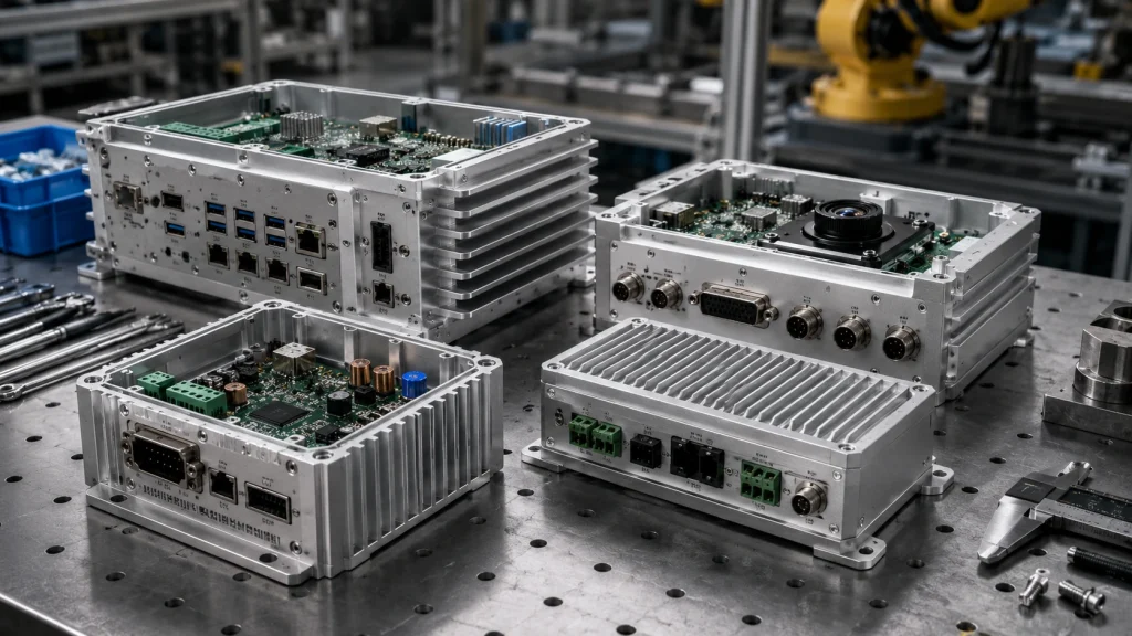
A well-designed enclosure can locate the PCB and connectors, provide a heat path, support grounding and shielding, control gasket compression and transfer mounting loads into the machine frame. Effective industrial electronics enclosure machining starts with those system requirements and then turns them into material, geometry, finishing and inspection decisions.
Why CNC Aluminum Enclosures Fit Industrial Electronics
A custom CNC aluminum electronics enclosure becomes useful when the mechanical housing starts to influence electronic performance or assembly.
Typical applications include edge AI computers, machine-vision controllers, robotic control modules, industrial gateways, DAQ systems, compact I/O hardware, sensor hubs and power-electronics assemblies.
Compared with a generic box, a machined enclosure can integrate:
- PCB standoffs and locating bosses
- Connector openings on several faces
- Gasket grooves
- Thermal contact pads
- Sensor and optical apertures
- Cable-entry geometry
- Machine-mounting features
- Internal ribs and pockets
These features can share a common datum system rather than depending on separate brackets and panels.
A commodity enclosure still makes sense where the electronics only require basic containment and simple cutouts. CNC becomes more attractive as the enclosure takes on structural, thermal, sealing or electrical functions.
For example, a machine-vision controller may require camera connectors on three faces, a processor seated against a thermal pad and a sealed service cover. At that point, the enclosure becomes part of the product architecture.
Choosing Aluminum and the Right Enclosure Process
6061-T6 and T651 are common starting materials for billet-machined electronics housings because they combine machinability, useful stiffness, corrosion resistance and good finishing options.
The temper suffix can matter on heavily pocketed parts. BOONA guide to 6061-T6 vs 6061-T651 explains why T651’s mechanical stress-relief step can provide a better starting condition for parts with large pockets, thin floors or extensive asymmetric material removal.
6063 becomes more relevant when the enclosure starts from an extrusion, especially for long constant-section housings or finned profiles. Sheet alloys such as 5052 often suit fabricated cabinets better than deep billet machining. Higher-strength 7075 deserves consideration only where the actual load case requires it.
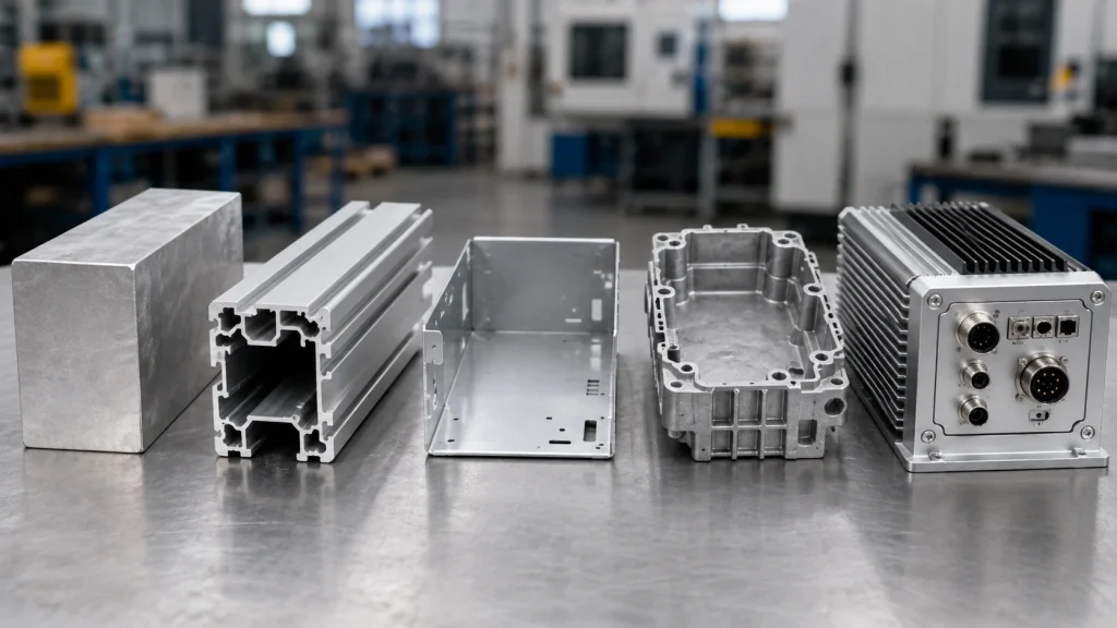
Process selection should follow geometry as well as production volume.
| Requirement | CNC Machining | Extrusion | Sheet Metal | Die Casting |
|---|---|---|---|---|
| Integrated bosses | Excellent | Limited by profile | Usually separate | Good |
| Deep custom pockets | Excellent | Limited | Weak | Good |
| Gasket grooves | Excellent | Secondary machining | Moderate | Good |
| Multi-face connectors | Excellent | Secondary machining | Good | Secondary machining |
| Low-volume design changes | Excellent | Moderate | Excellent | Expensive |
| External cooling fins | Good | Excellent | Limited | Excellent |
| Large thin housing | Material-intensive | Moderate | Excellent | Application-dependent |
| Upfront tooling | Low | Profile tooling may apply | Low | High |
CNC is especially strong where geometry is still evolving and several functional interfaces need to remain accurately related.
Deep Pockets, Thin Walls and Multi-Face Machining
A billet enclosure can lose most of its original material before completion. The remaining thin walls, broad floor and narrow connector panels may then respond to residual stress, clamping force and cutting loads.
Typical risks include base bowing after fixture release, wall vibration during finishing and position changes around heavily pocketed connector faces.
DFM should therefore review:
- unnecessary wall thinning
- large unsupported floors
- asymmetric material removal
- practical internal corner radii
- tool access
- clamping areas
- roughing versus finishing sequence
- free-state inspection requirements
Connector-rich housings also create setup challenges. A rectangular controller may need features on the front, rear, sides and top, all referenced to the PCB inside.
For suitable geometry, 5-axis CNC machining can improve tool access and reduce unnecessary repositioning. The main benefit is often fewer setups and better access rather than an automatic improvement in tolerance.
💡 Pro Tip: Define whether critical flatness applies in the free state, bolted to a machine frame or fully assembled. Those three conditions can produce different inspection results.
Thermal Management in CNC Aluminum Enclosures
Good aluminum enclosure thermal management depends on a complete conductive path.
A processor does not cool effectively simply because the enclosure is aluminum. Heat must move through defined interfaces, for example:
processor → heat spreader → thermal interface material → machined enclosure pad → enclosure exterior → ambient environment.
CNC machining can integrate thermal contact pads, heat-spreading sections, fins and structural mounting surfaces into the same part. Flatness and surface condition at a thermal interface may therefore matter much more than on a nearby cosmetic wall.
Sealing makes the problem harder. A vented controller can exchange air with its surroundings, while a sealed rugged aluminum electronics enclosure may rely much more heavily on conduction through the chassis.
A 2025 peer-reviewed thermal study of a fully enclosed ruggedized computer evaluated its temperature field across an ambient range of 25°C to 55°C.
That range illustrates why thermal DFM should start from the expected deployment environment and internal power sources rather than assuming room-temperature bench conditions.
Published Case: Edge AI at −20°C to +40°C
A 2026 peer-reviewed Jetson AGX Orin outdoor-enclosure study provides a useful example of workload-dependent enclosure thermal behavior.
Researchers installed the computing module in a realistic closed outdoor enclosure with power supplies, LTE hardware and thermostat-controlled cooling, then tested it at chamber setpoints from −20°C to +40°C.
At the +40°C setpoint, the synthetic CPU/GPU stress workload reached approximately:
- 95.6°C GPU
- 99.0°C CPU
- 36.5 W average Jetson power
Under the same ambient condition, a YOLOv8s TensorRT FP16 inference workload sustained approximately 108.8 FPS at 19.1 W and remained below the thermal-throttling threshold.
The same enclosure therefore experienced very different thermal loads depending on the software workload.
For industrial enclosure development, this is the useful lesson: processor model and maximum power specifications alone cannot define the real thermal requirement. Ambient temperature, workload, power electronics, communication hardware, internal placement and cooling strategy all matter.
This is a published research example, not a BOONA customer project, and its temperatures should not be reused as universal design limits.
IP Sealing, Gaskets and Coolant Exposure
Industrial electronics may encounter dust, machining debris, humidity, coolant mist, splashing liquids or outdoor moisture.
The current consolidated IEC 60529 IP Code classifies degrees of protection provided by electrical-equipment enclosures against access, solid foreign objects and water.
Machining can influence the sealing architecture through:
- gasket groove width and depth
- sealing-land condition
- corner transitions
- cover flatness
- screw spacing
- cable glands
- connector penetrations
- vent interfaces
A groove can meet its local dimensions and still seal poorly if the cover bows or fastener spacing produces uneven gasket compression.
Industrial connectors deserve particular attention because a port can become the weakest point in an otherwise well-sealed enclosure. Connector seals, cable entries and assembly torque belong to the complete system.
CNC machining can create geometry intended for an IP-rated design. The IP classification itself belongs to the final tested configuration, including cover, gasket, connectors, vents, fasteners and cable entries.
That boundary should stay clear on drawings and supplier documentation.
EMC, Grounding and Empty-Enclosure Shielding
Factory electronics may operate close to VFDs, servo drives, contactors, switching supplies, motors and long cables. These environments make enclosure seams and electrical interfaces part of the EMC discussion.
IEC 61000-6-2:2016 applies generic EMC immunity requirements to electrical and electronic equipment intended for industrial locations when no applicable dedicated product or product-family immunity standard exists.
Machined features that can support the enclosure side of the EMC design include:
- grounding studs
- connector-shell bonding
- conductive gasket lands
- controlled cover seams
- fastening locations
- aperture geometry
- bare-metal contact areas
Electrostatic discharge belongs to the same system-level evaluation. The current IEC 61000-4-2:2025 is the third edition of the basic ESD immunity test standard for electrical and electronic equipment.
There is also a specific enclosure-level distinction. IEC 61000-5-7:2001 defines methods for evaluating shielding provided by empty mechanical enclosures between 10 kHz and 40 GHz.
An empty enclosure shielding result does not establish complete-equipment EMC compliance. PCB design, cabling, filters, connectors and grounding architecture remain part of the final system.
Connectors, Vibration, Mounting and Anodizing
A practical industrial enclosure has to account for the way technicians install and cable the equipment.
Interfaces may include M8 or M12 circular connectors, industrial Ethernet, D-sub, RF ports, power connectors and cable glands. Each brings requirements beyond the cutout itself.
Design review may need to consider:
- panel thickness
- mounting-hole position
- anti-rotation features
- gasket seating
- wrench and nut clearance
- cable bend radius
- connector spacing
- shell grounding
Mounting loads also matter. A controller fixed to a moving machine or robot experiences a different environment from electronics sitting in a stationary cabinet. The customer’s actual vibration and shock requirements should govern the enclosure design; there is no universal industrial vibration level that applies to every housing.
Surface finish adds another interaction. Anodizing supports corrosion resistance and wear protection, but anodic oxide is electrically insulating compared with bare aluminum.
Grounding pads, connector bonding surfaces and conductive cover interfaces may therefore require masking or another defined contact strategy. Drawings should clearly separate cosmetic surfaces from electrical contact areas and finish-sensitive dimensions.
Inspection, Drawing Review and Supplier Selection
Inspection of CNC aluminum enclosures should follow system function rather than only checking isolated dimensions.
Typical checks can include:
- mounting-base flatness
- PCB standoff position
- connector opening location
- thermal pad geometry
- gasket groove position
- cover alignment
- grounding lands
- threaded features
- critical post-anodize dimensions
CMM inspection can verify relationships across several enclosure faces. Optical measurement, thread gauges and functional mating fixtures can address smaller or application-specific features.
Common drawing problems include connector openings referenced from cosmetic walls instead of PCB datums, thermal pads with no reference to the heat source, anodizing with no masking instructions and sealing grooves without a defined mating condition.
Another mistake is assigning complete-system claims such as IP67 or EMC compliant to the machined component without defining the geometry that the CNC supplier actually controls.
For procurement, a useful supplier review should ask whether deep-pocket geometry, multi-face datums, sealing surfaces, thermal interfaces and post-finish dimensions can be reviewed before material is cut.
FAQs
Why use aluminum for industrial electronics enclosures?
Aluminum combines useful rigidity, relatively low density, machinability, corrosion resistance and thermal conductivity. Its electrical conductivity can also support grounding and shielding strategies when seams and contact surfaces are designed correctly.
What aluminum is commonly used for CNC electronics enclosures?
6061-T6 and T651 are common candidates for billet-machined housings. The correct choice depends on stock form, machining depth, structural loads, finishing and dimensional-stability requirements.
How do CNC aluminum enclosures dissipate heat?
The enclosure can become part of a conductive heat path from the electronic component through a heat spreader or thermal interface material into a machined housing surface and then to the surrounding environment.
Can a CNC aluminum enclosure be IP67?
CNC machining can create gasket grooves, sealing lands and connector interfaces designed around an IP67 target. The final assembled configuration still requires the appropriate validation testing to establish the rating.
Does anodizing affect EMI shielding?
Yes, at electrical contact interfaces. Anodic oxide is insulating, so grounding pads, conductive seams and connector-shell bonding areas may require masking or another controlled contact treatment.
When should I choose CNC instead of extrusion?
CNC is especially useful for evolving or lower-volume designs with custom internal pockets, integrated bosses, multi-face connectors, sealing grooves and thermal pads. Extrusion becomes more attractive when a constant cross-section dominates the housing geometry.
Conclusion: Design Around the Electronics and the Environment
Successful CNC aluminum enclosures are designed around both the electronics inside and the industrial environment outside.
PCB position, connector geometry, thermal transfer, gasket sealing, grounding, EMC interfaces, machine mounting, anodizing and inspection can all interact within the same housing. A change that improves cooling can complicate sealing. A coating selected for corrosion protection can interrupt an electrical bond. A thin wall chosen to save mass can affect flatness or connector stiffness.
A stronger RFQ therefore provides the CAD model, controlled drawing, PCB or connector reference geometry, thermal requirements, target ingress-protection level, mounting method and surface-finish specification.
For a custom enclosure project, send these files through BOONA Aluminum CNC Machining service for a manufacturability review. No MOQ. Send your CAD for a free DFM review.


