
An upright’s last weight-saving pocket can remove the stock intended for clamping. The revised geometry may then need a different fixture, longer tools, or another setup to finish its bearing and suspension interfaces. A mass target alone cannot resolve those manufacturing decisions.
Machining Motorsport Uprights, brackets and billet parts requires coordinated control of material condition, functional datums, stock removal, finishing, and inspection. Start with the interfaces that carry load or locate mating components. Then choose a manufacturing sequence that preserves their relationships through the finished condition.
The component drawing establishes what the supplier must deliver. Loads, fatigue targets, and vehicle validation remain engineering responsibilities that need their own evidence. A dimensional report and a material certificate answer different questions from a suspension durability test.
Machining Motorsport Uprights: Which Features Carry the Function?
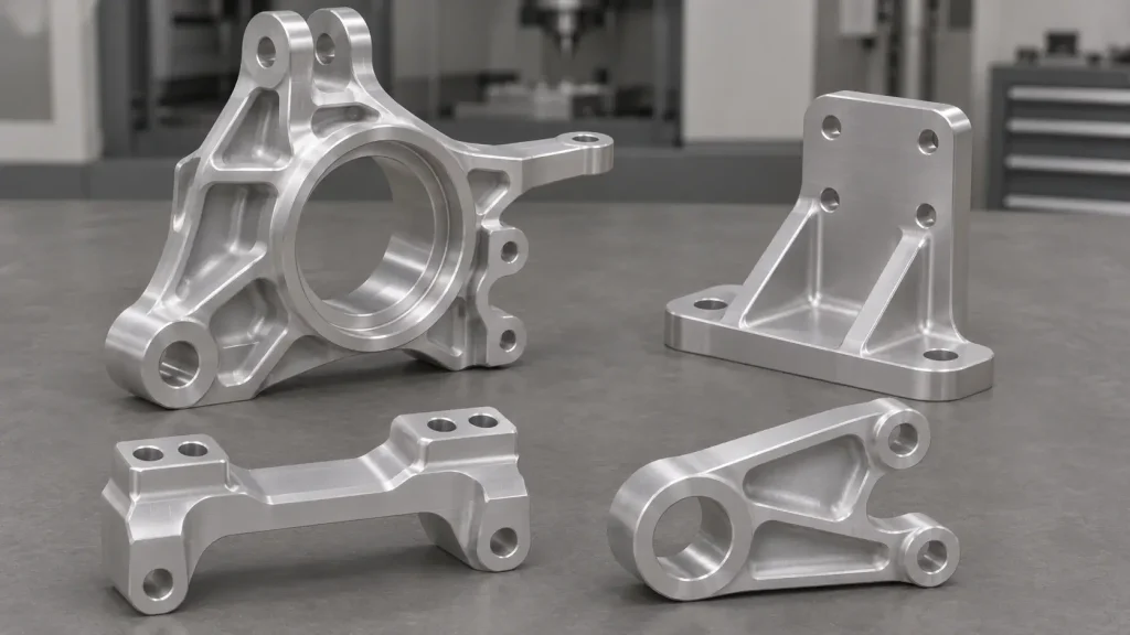
Suspension Uprights and Wheel-End Components
An upright connects the wheel-bearing assembly to suspension and steering interfaces. Its caliper mounts also introduce braking reactions. Bearing seats, retention shoulders, and pickup locations therefore need a shared geometric definition.
A bore diameter measured independently tells little about its relationship to the suspension pickups. The drawing should establish the bearing axis and the surfaces or features that locate the remaining interfaces. Front and rear parts may require different treatment because their steering, drive, and retention arrangements differ.
Brackets, Rockers, and Billet Accessories
Bracket requirements depend on function. A caliper bracket controls mounting offset and face relationships. An accessory bracket may need adjustment travel, while a rocker depends on the relationship between pivot and bearing features.
Use the following framework when identifying inspection priorities:
| Component | Interfaces to prioritize | Manufacturing concern | Acceptance evidence |
|---|---|---|---|
| Upright | Bearing seat and suspension pickups | Related geometry across setups | Datum-based dimensional report |
| Caliper bracket | Mounting faces and bolt pattern | Offset and face orientation | Inspection against defined mating datums |
| Suspension rocker | Pivot and bearing features | Bore relationships and distortion | Bore, form, and position measurements |
| Accessory bracket | Mounting pads and adjustment features | Stable seating and tool access | Interface and mounting-face inspection |
Separate locating features from fastening clearance. Include installation-tool access and the space needed to replace a bearing or remove a fastener.
Select the Alloy, Temper, and Stock Route Together
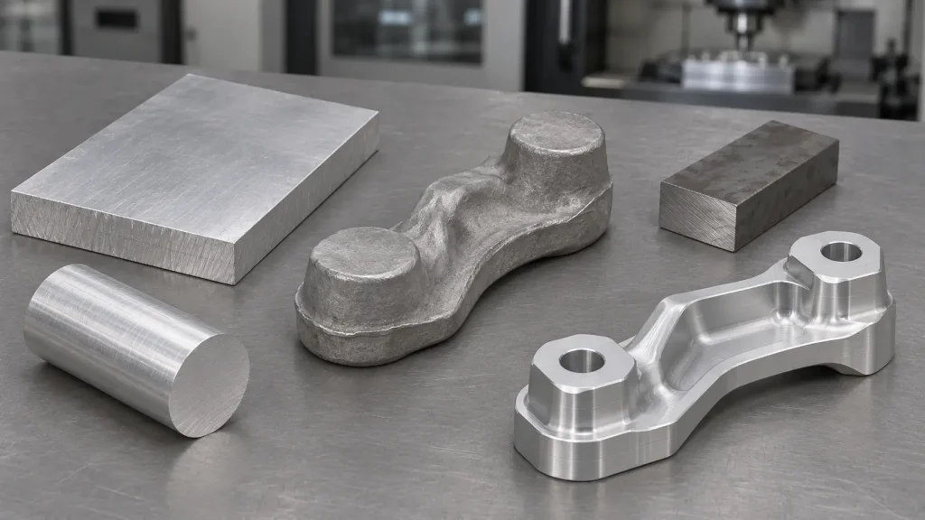
Compare Materials Against the Component’s Function
Candidate aluminum grades include 6061, 6082, and 7075, but an alloy name alone leaves the purchase specification incomplete. Define the condition, product form, and applicable material requirements before comparing quotations.
Separate strength from stiffness and fatigue behavior. A stronger alloy does not automatically resolve deflection, joint movement, or a fatigue-critical transition. Temperature exposure near braking hardware and corrosion conditions also belong in the engineering review.
Steel or titanium may deserve consideration where the design requires different strength, stiffness, temperature behavior, or packaging. Any material change needs review of the surrounding assembly, including mating materials and fastening arrangements.
Define What “Billet” Means in the Purchase Specification
In commercial usage, billet parts commonly means components machined from solid stock. Request the actual stock form and processing history rather than accepting that description as a material specification.
Discuss residual stress and stock orientation where they affect the design. Keep material identifiers connected to cut blanks and finished components. Later heat treatment needs its own process records and inspection plan.
BOONA aluminum CNC machining service is the relevant starting point for reviewing aluminum stock and manufacturing requirements. A forging, casting, and solid-stock version can require different geometry and validation; replacing the original route deserves a design decision.
Machining Motorsport Uprights: Datums, Fits and Tolerances
Build Datums Around Assembly Function
Define how the component sits in the assembly and how inspection reproduces that reference. Position and orientation requirements should connect the bearing axis to the relevant pickups and mounting faces.
For a BOONA upright RFQ, our recommendation is to supply the bearing designation and identify the locating shoulder before choosing the seat-finishing operation. A nominal bearing diameter leaves retention, installation direction, and the surrounding assembly requirements unresolved.
Mirrored parts need particular care. Release distinct handed drawings where appropriate, and identify asymmetric steering or caliper features explicitly. Similar-looking bearing housings can conceal different offsets.
Specify Fits and Finished Dimensions
Select fits from the actual bearing arrangement, loading, temperature range, and installation method. A generic interference-fit recommendation cannot establish retention or operating clearance for every upright.
Specify relevant bore form and surface condition alongside size. Address shoulders, thread engagement, and lead-ins. Identify whether inserts arrive installed and which checks occur afterward.
Coating can change a precision interface, so the drawing must identify the finished acceptance condition. Avoid applying the tightest tolerance to every pocket and external profile; focus inspection on features that control function.
Pro Tip: Identify which features locate the assembly and which only provide fastening clearance before tightening their tolerances. A precisely positioned clearance hole cannot compensate for an undefined locating interface.
Plan Machining Around Access, Support and Distortion
Choose the Setup Strategy
Choose conventional setups, indexed machining, or simultaneous five-axis machining according to access and feature relationships. Machine configuration alone does not establish final accuracy.
Our DFM recommendation for BOONA RFQs is to agree when sacrificial holding features disappear. Removing a useful grip before finishing related bores can force another datum transfer. Keep that decision visible in the manufacturing plan.
Sequence Roughing and Finishing Deliberately
Retain support during bulk removal and plan checks before finishing critical interfaces. Thin webs and deep pockets need attention to tool reach, cutting-force direction, and chip evacuation. Evaluate geometry after releasing the machining clamps where the acceptance condition requires it.
Application Example: Aerospace Structural Machining
A 2022 adaptive-fixturing study investigated a pocketed Ti-6Al-4V structural demonstrator for aerospace manufacturing. Section 4.2, Figure 12 reports mean bottom-surface flatness decreasing from 575 µm to 37 µm when comparing conventional one-sided machining with an adaptive fixture and double-sided machining route.
The latter route included releasing and reclamping after roughing. Both the fixture and sequence changed; attributing the result to the fixture alone would misrepresent the comparison.
The researchers deliberately created a high-residual-stress material condition. This was a demonstrator, not flight-qualified hardware, and it was neither a BOONA project nor evidence of BOONA capability. Our engineering inference for motorsport parts is to evaluate the fixture, release steps, and finishing sequence together. The reported improvement is not a transferable aluminum tolerance or production guarantee.
Coordinate Surface Treatment, Assembly and Inspection
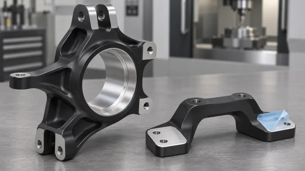
Protect Functional Surfaces During Finishing
Define which surfaces receive coating and which remain masked. Bearing seats, threads, and mounting lands may need different treatment. Agree allowances with the finisher before setting machining targets.
Control burr removal at intersecting holes and edge treatment around loaded transitions. Unspecified hand blending can alter a designed fillet or remove material that the stress analysis assumes remains present.
Finishing also affects more than fit. In a 2023 study of anodized 7075-T6 fatigue behavior, Section 3.4, Figure 6b reports endurance limits of approximately 180 MPa for unpeened anodized specimens and 400 MPa for specimens given the study’s high-intensity micro-shot peening treatment before anodizing.
These were laboratory rotating-bending specimens, not uprights. This was not a BOONA project and does not evidence BOONA capability. Our engineering inference is that surface preparation and coating sequence belong in fatigue validation. Those values establish neither a component allowable nor a universal recommendation to add peening.
Separate Different Types of Evidence
Use this handoff framework to prevent a component report from carrying claims beyond its scope:
| Evidence stage | What it establishes | What needs separate assessment |
|---|---|---|
| Material records | Specified grade, condition, and traceability within their scope | Finished geometry |
| Component inspection | Conformity to agreed dimensional and surface requirements | Installed behavior |
| Assembly verification | Seating, retention, and installation under defined conditions | Full operating-load coverage |
| Engineering validation | Performance under the defined analysis or test program | Conditions outside that program |
Agree any specified nondestructive examination, its timing, and its acceptance criteria before finishing and shipment.
Build an RFQ That Supports Comparable Quotations
Supply the Information That Changes the Manufacturing Plan
Send controlled CAD and drawings together. Include material condition, critical datums, mating-component details, finishing boundaries, and required inspection records.
Identify separate handed quantities and spares. If a replacement must interchange with an existing assembly, supply its controlled interface definition. Matching an earlier sample without understanding wear or modification can reproduce the wrong geometry.
Distinguish a packaging model from a component intended for load testing. Purchasing teams should identify the intended build stage and who approves engineering changes.
Explain the Main Cost Drivers
Material removal, access, workholding, and verification can matter more than the outside envelope. Deep pockets and thin features may increase effort while adding little functional value.
Use a change-review matrix before accepting a cost reduction:
| Proposed change | Manufacturing consequence | Required review |
|---|---|---|
| Increase an internal radius | May improve cutter access and reduce tool reach | Check mating clearance and load path |
| Remove a holding feature | May require another fixture or setup | Review datum transfer and final geometry |
| Relax a tolerance | May simplify machining and inspection | Confirm assembly function |
| Change coating coverage | Changes masking and dimensional planning | Review wear, fit, and environmental exposure |
Ask the supplier to distinguish recurring part cost from dedicated fixtures and inspection setup. A fixture that supports both an initial batch and replacement parts can deserve a different purchasing decision from tooling needed for a single design revision.
FAQs
Is 7075 always preferable to 6061 for motorsport parts?
No. Compare the specified conditions against strength, stiffness, fatigue, corrosion, and temperature requirements. Geometry and joint design also affect performance. A material substitution needs engineering approval, even when the proposed alloy has higher published strength.
Are billet components stronger than forged or cast components?
The billet description does not establish that comparison. Alloy, processing history, orientation, geometry, and defects all matter. Assess the actual component and manufacturing route using appropriate material data, analysis, and tests rather than a marketing label.
Does an upright require five-axis machining?
That depends on access and feature relationships. Some designs suit indexed machining or conventional setups with dedicated fixtures. Others benefit from simultaneous tool movement. Ask how the proposed route maintains the required references and permits inspection of critical features.
How should bearing-seat tolerances be specified?
Start with the bearing arrangement and its manufacturer’s application guidance. Define retention, mounting direction, temperature conditions, and mating materials. Then specify size, form, surface requirements, and the final inspection condition. A bore diameter alone does not fully describe the interface.
Should bearing bores be masked during anodizing?
Masking is one option. The correct decision depends on required surface performance and the finished dimensional budget. Identify coating coverage explicitly and agree allowances with the finisher. Reinspect the relevant features after the operations that can change them.
What inspection documents should accompany machined racing components?
Request the evidence required by the drawing and purchase order: applicable material records, dimensional results, and specified processing or examination reports. Keep part identity and revision linked to those documents. They do not independently certify vehicle performance or competition eligibility.
Conclusion: Connect the Drawing to the Manufacturing Plan
Machining Motorsport Uprights successfully starts with defined interfaces and continues through stock selection, workholding, finishing, and verification. Brackets and other billet parts deserve the same connection between their function and their manufacturing requirements.
Before releasing an order, settle the final material condition, locating references, and coating boundaries. Identify which records support component acceptance and which assembly or durability checks belong to the engineering program. This gives purchasing and manufacturing teams a concrete scope to review together.
Send BOONA your CAD, controlled drawings, mating-interface details, and inspection requirements for a manufacturing review through our five-axis CNC machining service. We offer no minimum order quantity and a free DFM review. Include intended use and finishing requirements upfront so the team can assess the proposed machining route and documentation before you commit to production.