
A pressure sensor needs a route for the measured pressure to reach its sensing element. The electronics beside it need protection from water, road contamination, and cleaning fluids. Those requirements meet at the housing.
Machining automotive sensor housings therefore starts with a boundary map: where the design must remain closed, where it must transmit pressure or a signal, and which surfaces establish those interfaces. Aluminum provides a useful structural and thermal platform, while machining controls seal geometry, sensor location, and connector relationships.
Every additional opening complicates that map. The practical approach is to select the material and manufacturing route, control functional interfaces, coordinate finishing, and define acceptance at the actual delivery stage. Complete sensor sealing and qualification remain assembly-level responsibilities.
Define the Function and Environment of Automotive Sensor Housings
Design Around the Sensing Path
A housing for remotely connected electronics differs from a camera body, radar module, or direct-pressure sensor. Cameras need optical access. Radar needs an RF-compatible transmission path. Pressure measurement may require a media connection isolated from the electronics cavity.
Section 7 of the Texas Instruments radome design guide advises keeping metal structure outside the antenna’s field of view. An aluminum back housing may provide structural support and heat spreading while a separate radome handles transmission. The window pocket and retention geometry then become machining concerns.
Translate Installation Conditions Into Requirements
Specify the mounting location and relevant exposures before assigning a generic “sealed” requirement. A protected cabin module faces different conditions from a wheel-area sensor or an underhood assembly.
Identify the expected fluids and cleaning methods. Include temperature changes, vibration, and cable loads where relevant. Separate liquid-ingress resistance from condensation management: a protected pressure-equalization vent may serve a deliberate function. Its location, retention, and integration belong in the interface drawing.
Select Aluminum Stock and the Manufacturing Route
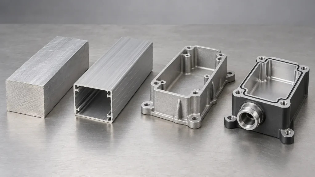
Billet Machining for Evolving Designs
6061 is a practical starting candidate for many machined housings. Specify its temper and stock form rather than leaving the drawing at “aluminum.” Where substantial pocketing makes dimensional stability important, discuss an appropriate stress-relieved stock condition. That choice cannot guarantee a distortion-free part.
Material selection also needs to account for corrosion exposure and the planned finish. Higher strength alone rarely resolves a poorly supported sealing flange.
Extrusions and Castings With Secondary Machining
Extrusion becomes attractive when the housing follows a constant cross-section. Casting can integrate geometry suited to a more stable production design, followed by machining of selected interfaces.
| Decision factor | Billet machining | Machined extrusion | Finish-machined casting |
|---|---|---|---|
| Design changes | Flexible | Constrained by profile | Constrained by tooling |
| Internal geometry | Limited by cutting access | Profile plus secondary features | Casting geometry plus finishing access |
| Sealing interfaces | Machined directly | Usually secondary-machined | Selected faces and seats machined |
| Material-integrity review | Stock condition and discontinuities | Stock condition and profile quality | Porosity and connected leak paths |
| Early cost emphasis | Stock removal and setups | Profile availability and machining | Tooling, casting quality, and machining |
This is a purchasing framework, rather than a ranking of universal process quality. Confirm whether the proposed route can produce and inspect the specific pressure boundary.
Map Every Seal, Port, and Sensing Interface
Cover Joints and Gasket Grooves
Treat the cover, gasket, fasteners, and housing as an interacting joint. Groove dimensions influence seal compression, while cover stiffness and fastening arrangement influence how consistently that compression develops.
Review continuity around corners and transitions. Obtain compression requirements from the selected sealing system. A general roughness callout cannot substitute for the seal geometry or cover design.
Connectors, Windows, and Vents
Each penetration introduces another interface. Connector seats require controlled location and support. Windows need retention features that preserve their sealing relationship under assembly loads. Vents require protected mounting seats and clear responsibility for installation.
Pro Tip: Identify every intentional opening before defining the leak-test setup. Plugging a vent or sensing port changes what the test actually verifies.
Process Pressure Versus Electronics Protection
For a direct-pressure sensor, distinguish the media-side pressure boundary from the electronics cavity. Follow cross-drilled passages through every intersection and closure.
A mounting screw can also become an unintended passage if its hole enters the cavity. Review thread depth, drill-point breakthrough, and remaining material explicitly. The outer appearance of a blind boss cannot establish that the cavity remains isolated.
Set Functional Datums, Fits, and Surface Requirements
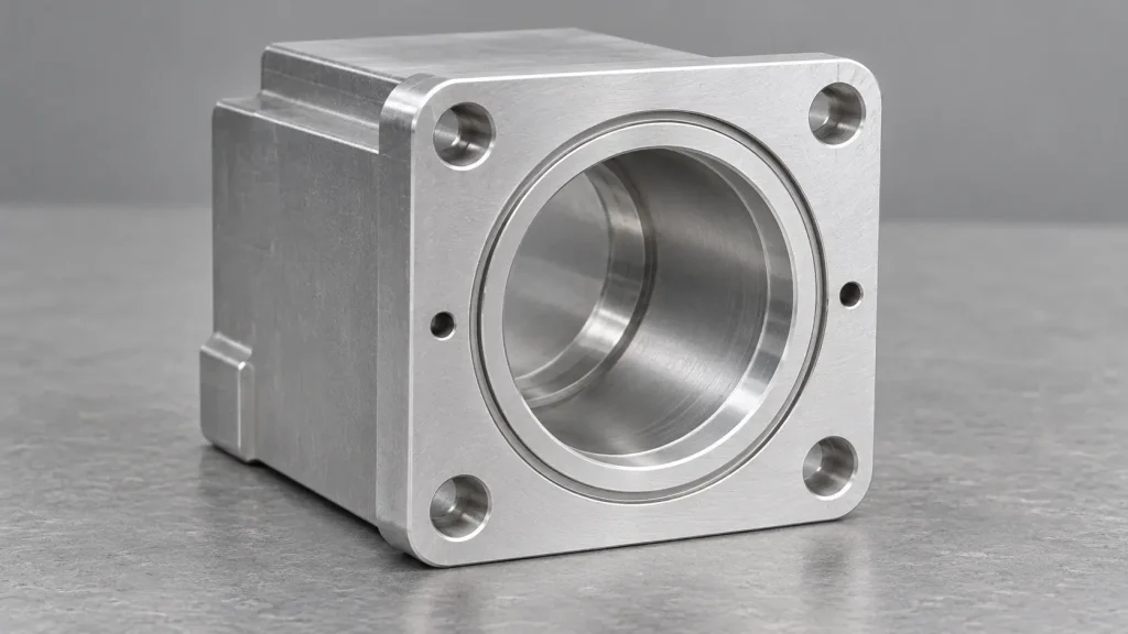
Relate the Sensor to the Vehicle Mounting Interface
Build the datum system around function. A camera’s optical-axis relationship, a sensing element’s locating bore, and a connector’s mating position may depend on different features.
Avoid referencing every critical dimension to an accessible cosmetic edge. Consider the load path through mounting bosses and how assembly restraint could influence sensitive internal interfaces.
For a BOONA RFQ, we recommend showing the connector’s seating face and rear retention access in the same interface detail. A port can be machinable while leaving no route to tighten the specified locknut or inspect the seal seat.
Specify More Than Surface Roughness
Sealing faces may require separate controls for form, local roughness, and permissible damage. A scratch crossing the sealing path presents a different concern from a machining mark elsewhere.
Define burr removal and lead-ins where seals pass over edges during installation. State whether critical fits apply after finishing. Also confirm that the selected inspection method can reach the controlled land without seating on an adjacent chamfer.
Plan Machining Around Thin Walls and Critical Features
Sequence Material Removal and Final Machining
Deep pockets can leave thin floors and narrow sealing flanges. Residual-stress redistribution and clamping loads can change their geometry during machining.
A useful sequence separates heavy stock removal from final work on critical interfaces. Intermediate checks help determine whether the next operation should reference the original stock or a newly established datum.
Our DFM recommendation for BOONA housing RFQs is to choose the final sealing-land operation before removing temporary clamping stock. If the remaining geometry offers only a delicate lip for gripping, the process plan already needs another locating strategy.
Control Tool Access and Edge Condition
Review narrow grooves, blind shoulders, and deep connector pockets for cutter reach and chip evacuation. Longer tools can increase machining difficulty even when the final dimensions appear ordinary.
Deburring access deserves its own review. An intersecting hole may leave an internal burr that is difficult to see and remove. Plan access without dragging a deburring tool across a finished sealing face. Specify cleanliness around passages and recesses where retained chips could later reach the seal.
Coordinate Coatings, Electrical Bonds, and Corrosion Protection
Protect Functional Interfaces During Finishing
Choose the finish alongside the machining plan. Coating growth can change fits, while masking creates transitions that need controlled locations. Discuss the appropriate process through BOONA surface finishing options.
Mark selected sealing lands, bores, and electrical contacts individually. Keep coating boundaries outside critical seating areas where practical. Review dissimilar-metal interfaces around fasteners and connectors rather than assuming a coated exterior resolves every corrosion concern.
Coordinate Internal Electronics Protection
Anodic oxide can interrupt an intended electrical contact. A conductive enclosure still needs defined bonding interfaces and sensor-level EMC validation.
Internal electronics protection also requires separate consideration. In a 2024 automotive pressure-sensor study, Section 3.5 and Figure 12c report normal output without significant upward or downward shifts after five additional temperature–humidity cycles following improved PCB conformal-coating uniformity.
That independent study was not a BOONA project and does not demonstrate BOONA capability. It investigated electronics protection, rather than aluminum machining. The engineering inference is to coordinate housing seals, moisture management, and internal protection without treating any single layer as complete sensor validation.
Inspect Automotive Sensor Housings at the Correct Delivery Stage
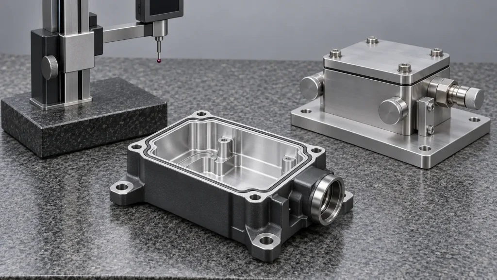
Separate Geometry Checks From Functional Testing
Agree the support or restraint condition for dimensional inspection. After finishing, verify critical dimensions, masking boundaries, and surface condition again where the process could affect acceptance.
For any component leak test, define the medium, pressure conditions, stabilization procedure, acceptance criterion, and temporary closures. Fixture seals can influence the result.
ISO 20653:2023 addresses ingress protection for road-vehicle electrical-equipment enclosures. ISO currently lists this edition as published, with revision work underway. An assembled configuration requires the applicable validation; component dimensions or an unrelated leak screen cannot establish its rating.
Use this interface-to-evidence checklist to define the handoff:
| Interface | Component evidence | Further validation |
|---|---|---|
| Cover joint | Land form and groove geometry | Assembled sealing performance |
| Connector seat | Position, support, and retention geometry | Connector-and-housing ingress behavior |
| Window pocket | Seat geometry and surface condition | Signal transmission and sealed retention |
| Vent seat | Port geometry and cleanliness | Vent function and ingress protection |
| Process connection | Passage integrity and sealing seat | Specified pressure-boundary performance |
Application Example: Pump Monitoring in Hot Oil
A 2023 oil-and-gas accelerometer encapsulation study illustrates the limits of screening conditions. Its “Leak testing” subsection reports no detected leakage in three housings after a week of room-temperature water and oil testing. In oil at 150°C, the commercial comparison housing showed traces within 24 hours and substantial ingress after a week, associated with supplementary Figure S9. The developed epoxy/FKM housings showed negligible traces after a week, associated with Figure S10.
The comparison housing was not designed to be leakproof; the researchers had added sealant tape and a rubber washer. This independent polymer-packaging research was not a BOONA project and provides no evidence of BOONA capability or aluminum-machining performance. The engineering inference is to validate the actual fluid, temperature, and exposure duration rather than extrapolating from room-temperature screening.
Build an RFQ That Separates Cost From Risk
Information Buyers Should Supply
A useful sensor-housing RFQ includes:
- Controlled CAD and drawing revisions.
- Alloy, temper, and stock-form requirements.
- Sensor, connector, seal, and mounting-interface references.
- Functional datums and critical finished dimensions.
- Finish specifications and masking boundaries.
- Cleanliness, inspection, packaging, and test responsibilities.
- Prototype quantities and anticipated design changes.
Identify who supplies the mating components and who closes each interface. If a test requires a production connector or window, establish whether that hardware will accompany the housing order.
Cost Drivers Worth Reviewing
Deep cavities and small internal radii can increase tool-reach demands. Multiple setups add handling and datum-transfer work. Selective finishing creates additional preparation and inspection.
Review requirements that add cost without addressing the failure mode. Tightening an exterior dimension will not resolve an unsupported connector seal.
Separate component inspection from complete-sensor testing in the quotation. Ask for the proposed acceptance evidence at each delivery stage, including how critical surfaces will remain protected during transport.
FAQs
Which aluminum alloy suits automotive sensor housings?
6061 is a common starting candidate for billet machining. Final selection depends on stock form, required strength, corrosion exposure, stability, and finishing. Extruded or cast designs require their own material review.
Can a CNC sensor housing be IP67?
Machining can produce the sealing and connector interfaces intended for that target. The assembled configuration, including seals, penetrations, and installation conditions, still needs the applicable validation testing.
How does anodizing affect seals and precision fits?
It changes the finished surface and can alter dimensions. Specify final acceptance conditions and any masking. Seal compatibility and electrical-contact requirements should guide treatment of individual interfaces.
Can aluminum be used around radar, camera, or pressure sensors?
Yes, where the architecture preserves the sensing path. Radar may need a separate radome; cameras require optical access. Pressure sensors need a defined media interface and protection for adjacent electronics.
Is pressure-decay testing equivalent to water-ingress testing?
No. The media, pressure conditions, fixtures, and failure mechanisms differ. A screening method needs an established relationship to the required performance before it can serve as a production acceptance test.
When should a housing move from billet machining to casting?
Consider casting when the design stabilizes and its geometry, tooling investment, material integrity, and production requirements justify the change. Validate the cast-and-machined route independently.
FAQ schema to be generated via RankMath FAQ block — do not paste schema code in the body.
Conclusion: Specify the Interfaces That Determine Performance
Successful automotive sensor housings coordinate sensing access, mechanical location, and environmental protection. Clear drawings connect those functions to machining, finishing, and inspection. The handoff should state what the supplied component proves and which assembled-sensor tests remain.
If the design changes from billet to casting, or a connector or coating changes, revisit the affected boundary and its acceptance evidence. A previous test result remains tied to its tested configuration; it does not automatically follow the housing through every revision.
Send your CAD, controlled drawing, and sealing-interface requirements through BOONA aluminum CNC machining service. There is no minimum order quantity, and every quote includes a free DFM review. Ask us to review critical finished dimensions, tool access, and the proposed component acceptance plan before releasing the design.


