
Coat a shaft and its mating bore, and the finish consumes clearance from both directions: the shaft grows while the opening narrows. Compensating only the bore leaves the mating shaft’s contribution outside the calculation.
Type III Hardcoat Anodizing therefore requires a feature-by-feature allowance. Distinguish total oxide thickness from outward buildup, account for metal removed during preparation, and define dimensions in their final finished condition. A nominal growth estimate helps position the machining target; a tolerance budget determines whether the finished fit is achievable.
For precision aluminum components, the practical sequence is to select the required coating performance, identify surfaces that must remain uncoated, and agree on allowances with the finishing supplier before machining begins. Making the coating thicker can change both the dimensional budget and the surface’s behavior in service.
How Type III Hardcoat Anodizing Changes Dimensions
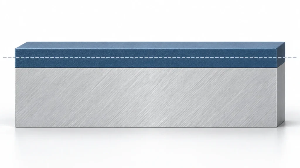
Total Coating Thickness vs Outward Buildup
Anodizing converts aluminum at the surface into oxide. Part of the resulting layer occupies space previously occupied by metal; another portion extends beyond the prepared surface.
In its General FAQ question, “Does anodizing alter the bolt/nut thread pattern and diameter?”, the Aluminum Anodizers Council gives a nominal Type III rule of half penetration and half outward buildup. The same answer warns that alloy, processing conditions, and chemical preparation affect dimensional change.
Use separate variables:
- t: total oxide thickness.
- g: outward buildup above the prepared metal surface.
- e: metal removed per surface during pretreatment.
The preliminary approximation is g ≈ t/2. Relative to the original as-machined surface, net outward movement is b = g − e.
Why the Nominal Ratio Needs Confirmation
“Prepared” means after dimensional effects from pretreatment, immediately before oxide growth. Confusing that condition with “as machined” can create a systematic allowance error.
Ask the finisher to confirm the expected net dimensional change for the specified alloy, geometry, and preparation route. External faces and recessed features may need different assessment. A thickness measurement on an accessible exterior surface does not establish coverage throughout a deep bore.
For a BOONA RFQ, our recommendation is to identify whether each critical dimension applies before or after finishing. Keep this decision attached to the drawing revision used for aluminum CNC machining.
Calculating Allowances for Bores, Shafts, and Slots
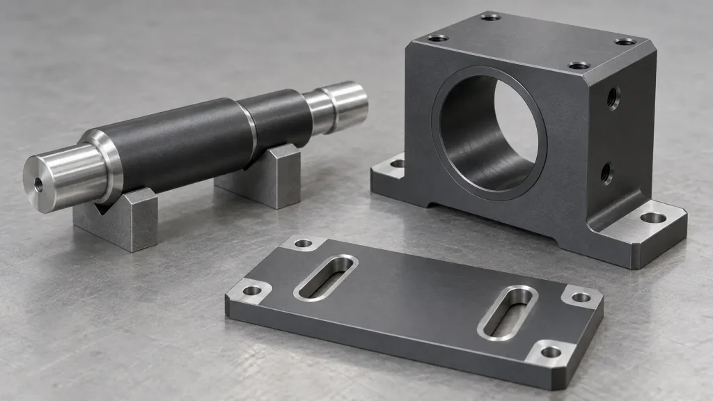
Feature-by-Feature Dimensional Changes
The following calculation framework assumes equal buildup g on opposing surfaces, measured from the prepared condition. It is a geometric planning model, not a coating acceptance specification.
| Feature | Nominal dimensional change | Allowance direction |
|---|---|---|
| External shaft diameter | Increases by 2g | Prepare the diameter smaller |
| Internal bore diameter | Decreases by 2g | Prepare the diameter larger |
| Slot with both walls coated | Width decreases by 2g | Prepare the slot wider |
| Plate with both faces coated | Thickness increases by 2g | Prepare the plate thinner |
| Single coated locating face | Surface moves outward by g | Offset relative to the datum scheme |
If opposing surfaces receive unequal buildup, replace 2g with their sum. For calculations starting from the as-machined condition, substitute net movement b, including pretreatment removal.
Worked Bore Example
Consider an illustrative finished bore target of 20.000 mm. Assume total coating thickness t = 50 µm and outward buildup g = 25 µm per wall.
The prepared bore target is:
20.000 mm + 2 × 0.025 mm = 20.050 mm.
This is the diameter after pretreatment and before anodizing. The as-machined target must also account for any enlargement caused by material removal during preparation. These figures are calculation assumptions, not BOONA tolerances or a universal coating recommendation.
When Both Mating Parts Receive Coating
Relative to prepared dimensions, diametral clearance decreases by 2g for the shaft plus 2g for the bore. Calculate the minimum finished clearance using the largest finished shaft and smallest finished bore.
Threads need a separate analysis of flank geometry and pitch diameter. Applying the plain-bore formula directly to a thread fit can produce the wrong allowance.
Building a Tolerance Budget That Survives Finishing
Nominal Compensation vs Process Variation
Moving the machining target compensates for expected growth. It does not remove variation in coating thickness, preparation, or measurement.
Extend the illustrative bore example. Assume total coating thickness of 50 ± 10 µm, an exact half-outward buildup ratio, and a prepared bore tolerance of ±5 µm. The coating contributes ±10 µm to the diameter change. Worst-case addition produces a final tolerance of ±15 µm, before other effects.
That calculation cannot substantiate a ±10 µm finished requirement. It excludes buildup-ratio uncertainty and local nonuniformity; pretreatment uncertainty must already be contained within the prepared-bore allowance.
Measured research reinforces this distinction. In the 2023 study by Winter and Lampke, Section 3.1.2, Table 7 reports that the hard-anodized condition targeting 20 µm averaged 22.4 µm, with measured minimum and maximum thicknesses of 8.3 and 33.6 µm.
Those results concern unsealed, laboratory-treated 6082 specimens. They are neither allowable production tolerances nor a measurement of outward buildup. This was not a BOONA project and does not establish BOONA capability. The engineering inference is to request local coating control where the fit actually occurs.
Application Example: A Satellite’s Telescopic Mast
A 2024 study of the SATech-01 telescopic mast documents manufactured hardware intended to position a magnetic probe away from the spacecraft. In “System design—Deployment strategy,” the text associated with the paper’s Figure 2 gives retracted and deployed lengths of 0.95 m and 5.28 m.
Under “Development of engineering prototype—Material selection,” the authors identify a hard-anodized aluminum first-stage sleeve.
For comparable telescoping hardware, binding during extension is a design risk worth assessing across the finished sliding interfaces. That is an engineering inference, not a failure reported for this mast.
The paper does not establish Type III specification compliance, coating-growth allowance, or a transferable fit tolerance. This independent project is not a BOONA project and does not evidence BOONA capability or imply that anodizing alone produced successful deployment.
Masking Threads, Contact Pads, and Precision Interfaces
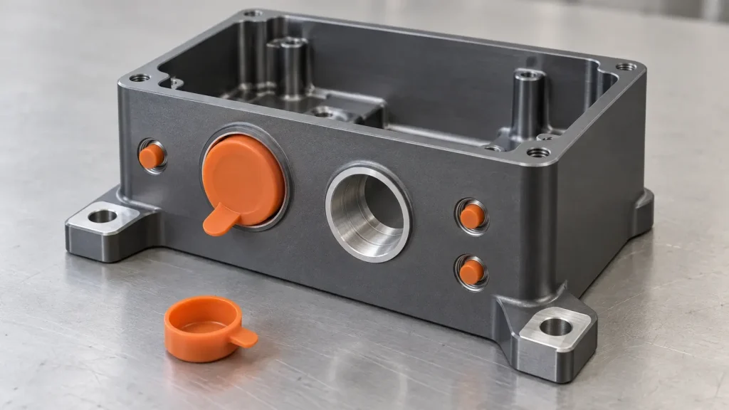
Decide the Finish State by Function
Masking can preserve a fit or conductive interface, but it also leaves an area without the surrounding hardcoat. Specify how that exposed region will meet corrosion and assembly requirements.
Use the following feature-state matrix as a purchasing framework, not a set of standardized quality grades.
| Interface | Decision to make | Evidence needed at acceptance |
|---|---|---|
| Sliding bore | Coat with allowance or use another interface design | Finished bore size, form, and specified coating condition |
| Threaded hole | Mask or approve a coating-compatible thread allowance | Thread-gage result in the required delivery state |
| Electrical bonding pad | Exclude insulating hardcoat where contact is required | Mask boundary and the specified contact-surface condition |
| Seal land | Select coating and texture for the actual seal system | Final profile, surface condition, and defect inspection |
| Bearing seat | Preserve the designed fit through an agreed finishing route | Finished size and relevant geometric measurements |
Keep Mask Transitions Away from Working Surfaces
Our DFM recommendation for BOONA drawings is to place a masking boundary outside a sliding contact path or seal footprint whenever the design permits. If it must cross a functional surface, define its permitted location and acceptance condition explicitly.
Pro Tip: Draw the allowable masking-transition zone, not just the nominal boundary line. A finish transition that shifts into a seal footprint can create a different interface even when the nearby bore diameter remains acceptable.
Also agree when masking occurs. Protection during anodizing does not automatically mean protection from every earlier cleaning or etching step. Reserve suitable rack-contact locations away from critical fits and seal paths.
Specifying Type III Hardcoat Anodizing on Drawings
State the Governing Requirements
The active U.S. specification is MIL-PRF-8625F with Amendment 2, dated 23 November 2020. Its document record can be located by searching the designation in DLA QuickSearch. A separate hard-anodizing specification is ISO 10074:2021. Do not treat the standards as interchangeable without reviewing contractual requirements.
The drawing and purchase order should identify:
- Governing specification and contractual revision.
- Aluminum alloy, temper, and relevant stock condition.
- Required coating type, class or color where applicable, and thickness limits.
- Sealing requirements and any approved subsequent treatment.
- Masked areas, transition zones, and acceptable rack-contact locations.
- Dimensions and geometric requirements that apply after finishing.
- Inspection locations and required records.
Avoid using “black anodize” as a substitute for the coating specification. Color alone does not establish hardcoat performance or thickness.
Connect Coating Performance to the Service Environment
A 2024 study of hard-anodized aluminum for hydrogen-valve applications illustrates why service conditions belong in the discussion. Section 3 of that paper, in the discussion of Figure 5, reports a wear depth of 2.05 µm for hard-anodized specimens under a 3 N dry-sliding test. Its discussion of Figure 8 reports 21.13 µm under the corresponding distilled-water condition.
These were laboratory sliding tests on sealed specimens, not complete-valve endurance tests. The study was not a BOONA project and does not establish BOONA capability. The engineering inference is to evaluate coating and sealing requirements against actual contact conditions before selecting thickness solely for dimensional convenience.
Assign Ownership of the Allowance
Keep final design requirements separate from manufacturing compensation. Agree who calculates the pre-finish targets and who approves changes to thickness, masking, or sealing.
If a bore finishes undersize, reaming can remove required oxide. Stripping and recoating can also alter the substrate. Require engineering disposition before either route becomes an informal production correction.
Inspection, Cost, and the RFQ Checklist
Inspect the State the Customer Will Receive
A coating report and a dimensional report answer different questions. Coating thickness alone does not establish bore size, and a passing bore measurement does not establish the specified coating properties.
Inspect critical dimensions after the final agreed finishing operations. Define whether datums are coated or masked, and use the required part support condition. On slender components, assess roundness or straightness separately from average diameter.
Agree how thickness will be checked where a probe cannot reach. A witness coupon can support process assessment, but it does not automatically reproduce the geometry or coating distribution of an internal feature. Identify any agreed correlation or additional evidence.
Where Cost Actually Accumulates
Cost can increase through detailed masking, restricted rack locations, difficult internal coverage, and additional inspection. Rework adds uncertainty because returning a part to its original metal geometry may be impossible.
For a BOONA quotation, our recommendation is to separate essential functional requirements from cosmetic preferences. Keep tight limits on the interfaces that govern assembly; give nonfunctional surfaces an appropriate, explicit acceptance range.
Send the following with the RFQ:
- CAD and a controlled drawing showing final dimensions.
- Material grade and temper.
- Mating-part dimensions and the required fit or operating clearance.
- Finish specification, thickness limits, and sealing condition.
- A masking map and acceptable contact-mark locations.
- Relevant load, motion, environment, and inspection requirements.
If the finishing process cannot fit within the dimensional budget, review the interface design before narrowing every machining tolerance.
FAQs
How much does hardcoat anodizing change a part’s size?
Outward buildup increases external dimensions and reduces openings. The actual net change also depends on pretreatment removal. Calculate each affected surface separately and confirm the process-specific allowance rather than assuming the entire oxide thickness grows outward.
Is coating thickness the same as dimensional buildup?
No. Total oxide thickness includes the portion formed within the original metal surface. Outward buildup describes only the portion extending above the prepared surface. A thickness certificate therefore cannot substitute for a finished dimensional inspection.
Should a bore be machined oversize before anodizing?
Usually an internally coated bore needs an allowance for narrowing. However, the as-machined target must also include pretreatment removal. Set the target from the finished requirement and the agreed process rather than applying a generic oversize value.
Can threaded holes receive hardcoat?
They can, provided the thread allowance, process, and final gaging requirements support it. Coating changes the thread flanks and available clearance. Masking may be more appropriate when maintaining the original thread fit takes priority over coating those surfaces.
Should bearing seats and electrical contacts be masked?
The answer depends on function. A bearing seat may retain coating if its final fit is controlled. Electrical bonding interfaces generally need a defined conductive contact condition. Specify any corrosion protection needed where hardcoat is excluded.
Can an anodized bore be machined back to size?
Only through an approved finishing or rework plan. Material removal may reduce or eliminate the required oxide at the working surface. Confirm both final geometry and remaining coating requirements before accepting the corrected component.
Type III Hardcoat Anodizing works best when the coating, machining allowance, and finished acceptance criteria form one coordinated plan. Send BOONA your CAD, mating-interface requirements, and finish callout for a review of the proposed manufacturing route. Explore our surface finishing options and request a free DFM review. BOONA has no minimum order quantity; the review can help identify allowance and masking questions before you commit to production.


