
A lens barrel’s seating shoulder establishes where the lens rests. The retaining ring supplies the holding force. If the ring bottoms against thread runout before reaching the lens, tightening it further cannot establish the intended retention. That small interface decision connects machining directly to optical assembly.
Machining optical components requires functional datums, appropriate material condition, controlled finishing, and inspection of the surfaces that position the optics. Buyers should specify the relationship between lens seats, detector interfaces, and system mounting features, then define which requirements apply after coating. This approach supports repeatable mechanical assembly while leaving focus, wavefront quality, and laser performance to the appropriate optical validation.
Here, we focus on machined mounts, barrels, housings, and related hardware used in imaging and laser systems.
Machining Optical Components: Define What the Part Must Do
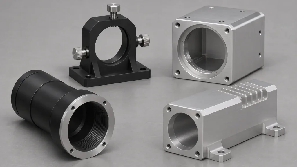
Common machined component types
Lens barrels locate optical elements radially and establish axial spacing through seats, spacers, or adjustable interfaces. Mirror-mount bodies support angular positioning. Camera housings connect the lens assembly to a detector carrier and the surrounding equipment.
Laser-module housings may also provide thermal contact, cable access, and attachment points. Baffles and aperture carriers control where light can travel through the assembly. Each component therefore needs a defined function before a drawing assigns its tightest tolerances.
A locating bore and a clearance passage can look similar in CAD while requiring different machining and inspection plans. A cosmetic exterior surface usually deserves different acceptance criteria from an optic-contact land.
Mechanical hardware versus optical surfaces
Manufacturing these components differs from producing the working surface of a lens or mirror. Diamond turning, optical polishing, and optical coating require separately specified processes and acceptance methods.
A smooth machined surface does not establish optical surface figure or laser-damage resistance. Where a metal component also serves as a reflective optic, the RFQ must identify that dual function explicitly. The optical prescription and surface acceptance requirements belong in the manufacturing package.
Select Materials for Thermal and Mechanical Stability
Aluminum for housings and mount bodies
Aluminum offers a useful combination of low mass, machinability, and heat conduction for many optomechanical structures. However, an alloy designation alone cannot settle dimensional stability.
Specify the temper and stock form alongside the grade. Substantial material removal can redistribute residual stress, particularly in thin-walled housings and asymmetrical brackets. Stress-relieved stock can help manage that risk, although geometry and machining sequence still matter.
When evaluating aluminum CNC machining, connect the material choice to the part’s wall sections, finished interfaces, and coating requirements. Higher strength alone does not guarantee lower thermal drift.
Steel, copper, and specialized materials
Stainless steel can suit wear-sensitive interfaces or retaining components. Copper can provide useful heat transfer where its mass and machining requirements are acceptable. Specialized low-expansion materials require a separate review of availability, condition, and processing.
Evaluate the assembled material combination
The optic, housing, fasteners, and supporting structure expand differently as temperature changes. Local heating from electronics or a laser source can also create temperature gradients.
Assess where relative movement is acceptable and where it changes alignment or contact pressure. A thermally stable assembly may require controlled compliance or adjustment. Simply tightening every interface more firmly can increase stress on the optic.
Translate Alignment Requirements into Drawing Controls
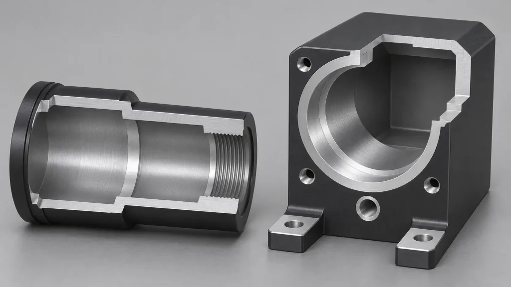
Establish a functional datum chain
An optical axis is a system reference. Manufacturing requires physical features from which to establish coordinates. Connect the lens-locating bore and seating shoulder to the housing’s external mounting interface.
For drawings using the ASME system, the current catalogue lists ASME Y14.5-2018, reaffirmed in 2024. State the governing edition and select geometric controls according to function.
The following framework helps distinguish what a feature does from what its inspection can establish.
| Machined feature | Functional contribution | Drawing and inspection focus |
|---|---|---|
| Lens-locating bore | Supports radial positioning | Size, form, and location relative to functional datums |
| Seating shoulder | Establishes axial seating position | Location, surface form, and orientation |
| Mounting pads | Connect the housing to the system structure | Pad relationships and defined inspection support |
| Detector-carrier interface | Positions the detector mechanically | Position, orientation, and adjustment provisions |
| Aperture carrier | Maintains the intended clear passage | Opening geometry and position |
These controls verify specified mechanical relationships. They do not independently establish the optical axis of an installed lens.
Account for retention and adjustment
For a BOONA drawing review, our DFM recommendation is to distinguish thread relief from the optic-seating surface. Confirm that the retaining ring reaches its intended contact before another feature stops its travel.
Include tool access and adjustment clearance. An interface that allows alignment before locking also needs a defined locking method and an assembly verification plan.
Choose the Machining Route Around Critical Interfaces
CNC turning for rotational components
Turning suits barrels, retaining rings, and stepped sleeves. Where access permits, producing related bores and seating shoulders in a common setup reduces dependence on subsequent datum transfer.
Internal features deserve particular attention. A deep narrow seat can restrict tool access, while interrupted cuts and thin walls complicate support. Thread relief must leave enough room for the specified mating component without reducing the seating land unintentionally.
Milling and multi-axis machining
Milling suits camera bodies, mounting structures, and non-rotational housings. Additional axis access can simplify angled interfaces or reduce some repositioning, depending on the geometry. Machine configuration alone cannot establish the finished relationship between features.
Our BOONA process-planning recommendation is to identify the optic-locating surfaces before choosing the fixture sequence. If those surfaces must transfer between turning and milling, agree how the next operation will reconstruct the datum reference.
Control distortion through sequencing
Roughing, intermediate release, and finishing may require separate stages. The route depends on stock condition and how much support remains as material leaves the part.
Check vulnerable geometry after release from the fixture where the drawing requires that condition. Burr control also needs access: a hidden burr at an internal shoulder can interfere with seating even when the bore diameter meets its specified limits.
Specify Finishing for Fit, Stray Light, and Cleanliness
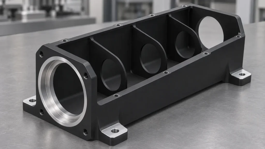
Mechanical finishes and dimensional allowances
Identify coated surfaces and masking boundaries before final machining. State whether critical dimensions apply before or after finishing, including internal threads and locating bores.
For a curved lens, the seating contact diameter also influences where the lens vertex lies relative to the shoulder. Preserve the intended contact geometry through deburring and finishing.
Evaluate optical blackening by application
Visual blackness provides limited information about performance at the operating wavelength. In a 2024 study of black-anodized aluminum and experimental carbon-nanofiber coatings, Section 2, Figure 4a–b reports average absorption of 96% over 250–670 nm for the tested black-anodized aluminum, compared with 66% in the paper’s near-infrared results.
Those measurements describe the study’s particular specimens. They are not universal values for black anodizing. This was independent university research, not a BOONA project or evidence of BOONA coating capability. Our engineering inference is to specify wavelength-relevant coating evidence instead of accepting color alone.
Surfaces receiving direct laser exposure require their own suitability assessment. A blackened housing surface does not establish beam-dump performance.
Define cleanliness explicitly
Specify allowable residue and the cleaning method where function requires it. Deep pockets, internal threads, and baffle features can retain chips or cleaning fluid. Vacuum compatibility and contamination limits require application-specific evidence.
Pro Tip: Show the seating contact diameter as well as shoulder depth for a curved lens. Changing that contact diameter can shift the lens vertex position without changing the machined shoulder depth.
Separate Component Inspection from Optical Validation
Verify the supplied component
Inspect the features that the drawing identifies as critical. A useful report connects each result to its datum reference and inspection condition.
Coating coverage, finished fits, and protected contact surfaces need separate checks where specified. A general material certificate cannot demonstrate that a lens seat meets its geometric requirements. Likewise, a dimensional report does not establish cleanliness.
Verify the assembled optical system
Focus, boresight, and wavefront measurements assess behavior beyond the machined component. Assign responsibility for alignment, locking, and environmental testing before ordering parts.
A representative mating fixture can check mechanical assembly, provided its role and acceptance limits are defined. It cannot automatically substitute for testing with the actual optics.
Application example: extended-depth-of-field imaging
A 2023 University of North Carolina at Charlotte imaging study illustrates the distinction. Section 2.2, printed page 772, describes optical housings machined from the same turned aluminum bar with a 63.5 mm outside diameter. The same section identifies ±50 µm as the smallest spacing tolerance among the studied configurations.
The bar diameter describes starting stock. The spacing value describes a design requirement, rather than a demonstrated general machining capability. The project investigated freeform phase plates for extended-depth-of-field imaging and evaluated optical behavior separately.
This was independent research, not a BOONA project or evidence of BOONA capability. The engineering inference is to preserve the required spacing through a defined mating-feature chain, then verify the optical result through the appropriate system test.
Machining Optical Components: Build a Useful RFQ
A useful RFQ connects the drawing to the assembly decisions that affect machining, finishing, and inspection. Include:
- Controlled CAD and drawings, with matching revisions.
- Component function and the relevant mating geometry.
- Material grade, condition, and permitted substitutions.
- Functional datums and alignment-related tolerances.
- Clear apertures and optic-contact geometry.
- Retention method, adjustment access, and locking provisions.
- Coating requirements, masking boundaries, and finished dimensions.
- Cleaning, handling, and protective packaging requirements.
- Required inspection records and responsibility for optical testing.
- Prototype quantity, repeat-order expectations, and likely design changes.
Treat tolerance allocation as a cost decision. Applying the tightest requirement to every surface can increase machining and inspection effort without improving the optical interface that matters.
For a BOONA RFQ, our recommendation is to identify which mating dimensions remain adjustable during assembly. A deliberately adjustable interface may need travel, access, and locking control rather than an unnecessarily restrictive fixed dimension.
Deep internal features and selective masking can also drive cost. Ask suppliers to explain the proposed route and inspection access when comparing quotations. Packaging should protect finished seats and bores without introducing fibers or adhesive residue onto controlled surfaces.
FAQs
Can conventional CNC machining produce optical-quality surfaces?
It can produce precision mechanical hardware. Optical surface figure, scatter, and wavefront requirements need separately specified fabrication and metrology. Surface roughness alone cannot establish that a reflective surface meets its optical prescription.
Which materials suit lens barrels and optical mounts?
Aluminum is a common candidate for housings and mounts. Selection should also consider thermal behavior, stock condition, wear, and finishing. Evaluate the complete material combination, including the optic and fasteners.
Does black anodizing provide sufficient stray-light control?
That depends on the operating wavelength, geometry, and permitted stray light. Specify relevant optical evidence where performance matters. A visibly black finish cannot establish the finished system’s stray-light behavior.
When does an optical housing need multi-axis machining?
Consider it when angled or complex interfaces benefit from improved tool access or fewer repositioning operations. A turned barrel or accessible housing may use a simpler route. Geometry and datum transfer should guide the choice.
How should tolerances account for finishing and temperature?
State which dimensions apply after finishing and define the relevant inspection condition. Evaluate thermal movement at assembly level, especially where dissimilar materials meet. Universal allowances cannot replace a reviewed tolerance plan.
Does a dimensional report prove optical alignment?
It verifies the mechanical requirements actually measured. Optical alignment depends on the installed optics, retention, adjustment, and system geometry. Define separate acceptance criteria for component inspection and assembled optical performance.
Conclusion: Specify the Interfaces That Control Alignment
Machining optical components starts with identifying how each physical interface contributes to the optical assembly. Material condition and machining sequence influence the geometry available for alignment. Finishing changes interfaces, while retention determines how the optic contacts them.
A practical specification connects those decisions to measurable acceptance criteria. Keep the component inspection plan distinct from optical validation, and identify adjustment provisions before assigning unnecessarily restrictive tolerances.
That distinction also makes supplier discussions more productive: the manufacturing team can review tool access and datum transfer, while the optical team retains responsibility for system-level performance requirements.
Send BOONA your CAD files, controlled drawings, material requirements, and acceptance plan for a CNC machining review. We offer no minimum order quantity and a free DFM review to help resolve machining access, critical interfaces, and finishing requirements before you order.