
Tightening an adjustable sensor mount can change the angle the installer has just set. Friction beneath a screw head can drag the bracket along its slot, while an uneven seating surface can tilt the sensor as the joint closes. The design needs a controlled way to establish and retain its position.
Machining LiDAR and ADAS brackets requires a defined datum chain, stable locating features, and a joint that retains its position after assembly. Choose material and geometry around the complete load path, finish the mating surfaces in their specified condition, and inspect the features that control sensor orientation. Vehicle-level calibration remains a separate task.
LiDAR is one sensing technology within ADAS. Camera, radar, and LiDAR mounts share mechanical concerns, but their viewing paths and installation requirements differ.
How LiDAR and ADAS Brackets Affect Sensor Alignment
Position, Orientation, and the Datum Chain
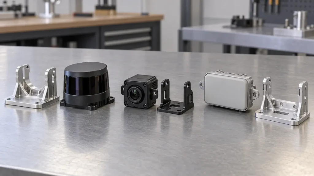
A bracket connects the vehicle mounting reference to the sensor’s mechanical interface. Position describes its location; roll, pitch, and yaw describe its orientation. The sensing frame may sit elsewhere inside the housing. Obtain the manufacturer’s mechanical-to-sensing-frame definition before treating an external face as an optical reference.
Hole position controls only part of that relationship. Mounting-pad orientation, sensor seating, and vehicle-side variation also contribute. The drawing should identify how the finished bracket establishes its reference frame during inspection and assembly.
A 2024 LiDAR–camera calibration study, Section 5.5, Figure 15, reports initial extrinsic-parameter deviations of approximately 0.3° in roll and 0.6° in pitch, with reported error below 0.1° after iterative calibration in that example. These are calibration results, rather than bracket tolerances or mechanical-retention measurements. The study was not a BOONA project and does not evidence BOONA capability. Our engineering inference is that small orientation differences deserve explicit treatment in the interface specification.
Allocate an Alignment Budget
Separate machining variation from assembly clearance, support movement, and calibration uncertainty. Assign each contribution an owner and an acceptance method. Also identify whether the requirement concerns initial installation or stability during operation; a static dimensional check addresses only the specified inspection condition.
For a hypothetical pointing calculation, lateral displacement is approximately R × tan(θ). An angular offset of 0.05° at 50 m gives about 44 mm. This calculated illustration excludes sensor measurement error and is not an allowable bracket tolerance. Work backward from the system requirement before selecting machining controls.
Choose Materials and Manufacturing Routes Around the Mounting Function
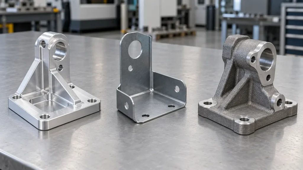
The useful comparison is between complete geometries and process routes. Material strength alone cannot predict orientation stability: section shape, unsupported length, and joint compliance also matter.
| Option | Reason to consider it | Main engineering question |
|---|---|---|
| CNC-machined aluminum | Integrated pads, locating features, and accessible design changes | Does the section provide sufficient stiffness? |
| Machined steel | Compact load-bearing features and durable interfaces | Are mass and corrosion protection acceptable? |
| Formed sheet metal | Efficient broad mounting shapes and economical material use | How will forming variation affect orientation? |
| Cast blank with secondary machining | Integrated geometry for an established design | Which interfaces require machining and inspection? |
Aluminum alloys such as 6061-T6 or 6082-T6 can be candidates for machined mounts. Selection still depends on the specified condition, environment, and geometry. BOONA aluminum CNC machining service provides a relevant route for reviewing these features against the supplied designf.
A steel design may accommodate a smaller structural section, while an aluminum design may benefit from deeper ribs or a shorter load path. Evaluate the actual assembly before comparing weight or manufacturing cost. Higher alloy strength alone does not establish greater elastic stiffness.
An entirely machined bracket becomes less attractive when it removes extensive stock merely to reproduce a simple folded shape. A formed structure with selectively machined interfaces may suit that application. Confirm that the chosen route preserves access for finishing the critical surfaces and measuring them afterward.
Also consider galvanic exposure at dissimilar-metal interfaces. A protective finish and a required electrical bonding contact need separate drawing treatment.
Design Locating Features That Survive Adjustment and Replacement
Separate Locating from Clamping
Clearance bolts provide assembly freedom. Dedicated locating features can establish repeatable position independently of screw clearance. Suitable arrangements may use a shoulder, locating pins, or controlled seating pads. Define the contacts that establish the primary seating plane and the features that control movement within that plane.
Avoid overconstraint. Several tight features can compete when the mating structure varies or expands thermally. Define which features locate each direction and which permit the intended movement.
Control Adjustable Interfaces
Slots need an explicit adjustment and locking strategy. Check washer support across the adjustment range, tool access, and the direction in which tightening tends to drag the bracket. Shims need supported contact areas and a defined retention arrangement.
For a BOONA RFQ, our recommendation is to identify whether the released CAD represents the nominal setting, an adjustment limit, or a fixed production position. This changes which surfaces need controlled relationships and whether a fixture must hold an angle during tightening. A slot endpoint should not silently become the locating datum.
Plan Service Replacement
Protect locating lands from handling damage and preserve access to the specified fasteners. State whether the acceptance requirement concerns first installation, retained alignment, or return to position after removal. These require different checks.
Pro Tip: Record sensor-mount position before and after the specified tightening sequence during assembly validation. A useful adjustment range does not establish how much the mount moves as it locks.
Sensor replacement may still require renewed adjustment and calibration under the applicable vehicle procedure, even when the mechanical interfaces repeat accurately.
Machine and Finish the Features That Control Alignment
Establish a Functional Machining Sequence
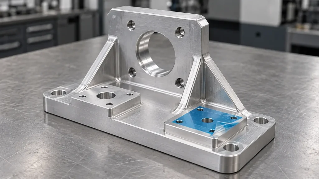
Plan heavy material removal before finishing the mounting pads. Thin webs and deeply pocketed sections need support that reflects how cutting and clamping forces enter the part.
For a BOONA DFM review, our recommendation is to place fixture support directly beneath the pad being finished. Clamping across an unsupported pocket can flex the section while the cutter generates an apparently continuous surface. Retaining temporary stock or changing the setup sequence may be preferable to increasing clamp force.
Where practical, finish sensor seating pads and their associated locating bores or shoulders in a common setup. When another setup is necessary, specify how the datum transfers. Additional machining axes can improve access, but they do not remove the need for a controlled reference system.
Apply Tolerances Selectively
Use orientation, position, or profile controls where the function requires them. A blanket tight linear tolerance can add cost while leaving the decisive angular relationship undefined. Specify seating-surface condition where tool marks, burrs, or local damage would affect contact.
Account for Finishing and Hardware Installation
Identify which dimensions apply after coating and insert installation. Keep masking transitions away from locating shoulders and loaded seating areas unless their effect has been accepted.
The drawing should distinguish a protected precision land from an electrical bonding pad. Those surfaces may have different finish requirements. Recheck critical interfaces after threaded inserts are installed, and protect exposed mating lands during subsequent handling and packaging.
Preserve Alignment Under Real Installation Conditions
Evaluate the Complete Load Path
A stiff bracket attached to a flexible panel can still rotate. Include the sensor mass, fastener arrangement, and supporting structure in the assessment. Cable routing also matters: a harness pulled into position during installation can apply a persistent moment at the sensor connector.
Shortening an unsupported arm or changing the support geometry may address movement more directly than tightening machining tolerances. Vibration assessment must consider the assembled configuration, including any isolation elements.
Consider Thermal Movement and Joint Behavior
Differential expansion can change seating loads or create constraint between the sensor and its support. Evaluate joint settling and the specified fastener preload alongside thermal movement. Keep sensing paths clear using the sensor manufacturer’s installation requirements.
Application Example: A Mine-Mapping Sensor Head
A 2026 underground hyperspectral-mapping study examined a rotating sensor head combining a hyperspectral camera and LiDAR. Section 3.2.5 explains that manual assembly onto a rigid frame could leave residual boresight misalignment. Section 4.1, Figure 7, reports corrections of −4.46° in azimuth and +0.19° in elevation. The same section’s Figure 4 addresses scan distortion associated with a lever-arm offset: a positional separation between reference points, rather than bending of the support.
This mining instrument is a different application from an automotive bracket. The reported angles are prototype-specific calibration corrections, not recommended mounting tolerances. It was not a BOONA project and does not establish BOONA capability. Our engineering inference is that a shared rigid frame still needs a defined relationship between measurement frames, particularly when sensors are removed and reassembled.
Specify and Inspect LiDAR and ADAS Brackets
Use a Four-Stage Acceptance Framework
Separate evidence about the supplied component from evidence about the installed sensing system. Agree which checks belong to the machining supplier and which require the integrator’s equipment.
| Acceptance stage | What to assess | Boundary of the result |
|---|---|---|
| Machined component | Geometry relative to the drawing’s datums | Component conformity |
| Finished component | Coated interfaces, inserts, and seating surfaces | Final supplied-part condition |
| Mounted assembly | Position after the specified tightening sequence | Installed mechanical position |
| Integrated system | Calibration and application-specific validation | Defined calibration and application-validation results |
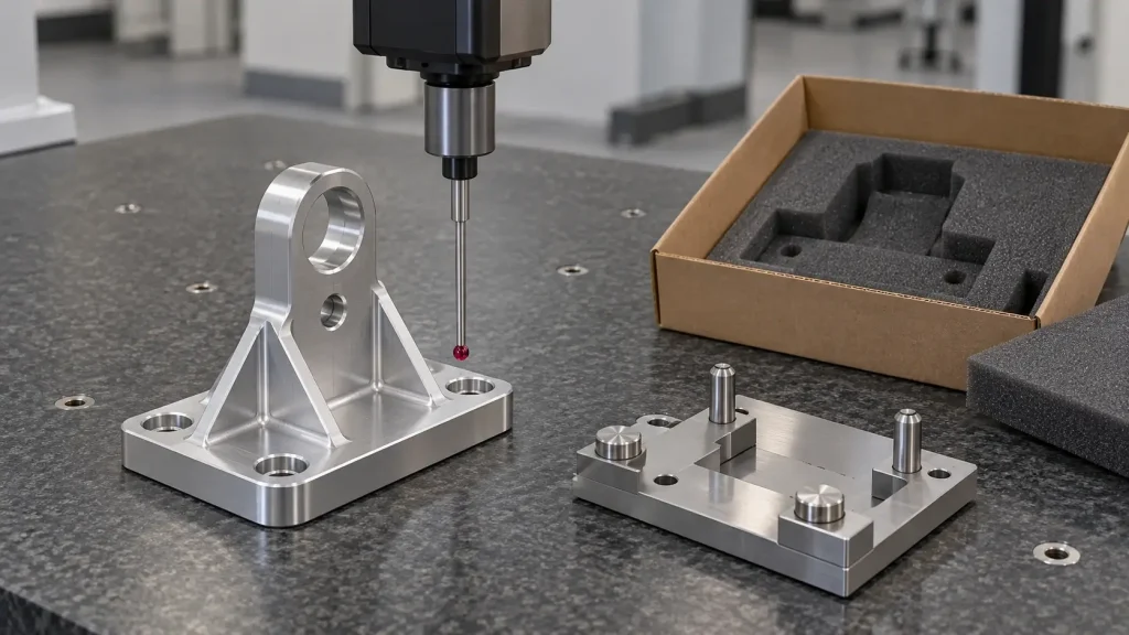
A coordinate measurement report should identify the datum alignment used. An inspection fixture should reproduce the intended seating contacts without introducing unintended constraint. If acceptance depends on a restrained condition, document that condition explicitly.
Demonstrating installation repeatability requires repeated assemblies under an agreed procedure; a single position measurement cannot establish it.
Build an RFQ Around the Interfaces
Supply the sensor interface drawing and vehicle-side mounting references. Include the material condition, finish boundaries, and final-state dimensions. Define the adjustment range separately from the permitted location after locking.
Request distinct checks for initial seating, movement during tightening, and return to position after removal if all are relevant. Specify the representative mating parts, assembly sequence, and measurement references needed for those checks. Otherwise, suppliers may price different inspection scopes against the same CAD model.
Also identify permitted processing-contact areas and packaging protection for locating lands. Include the drawing revision on the inspection requirements, and agree how any manufacturing deviation will be reviewed before shipment. A bracket report alone cannot establish completed ADAS calibration or vehicle safety performance.
FAQs
What tolerances do LiDAR mounting brackets require?
There is no universal value. Allocate the system alignment requirement across the sensor interface, bracket, supporting structure, and assembly process. Then apply dimensional and geometric controls to the features responsible for each contribution. Specify whether acceptance applies before or after finishing.
Can CNC machining eliminate ADAS calibration?
Machining can improve mechanical positioning and repeatability. Calibration establishes the relationship between sensing frames and the required system reference. Follow the applicable sensor and vehicle procedures; a compliant bracket does not independently establish a calibrated system.
Is aluminum suitable for automotive sensor brackets?
Aluminum can suit many mounting designs, provided the section geometry delivers the required stiffness and the assembly addresses thermal movement and corrosion exposure. Compare complete designs rather than selecting solely by alloy strength or material density.
Should a sensor bracket use dowels or adjustment slots?
Locating features favor repeatable positioning. Slots provide adjustment but need a defined locking method. Some assemblies combine both functions. Select the arrangement around installation variation, thermal behavior, and service requirements rather than assuming either option always improves alignment.
Can anodizing or powder coating affect alignment?
Coating can alter seating, locating clearances, and contact beneath fasteners. Define masking and final interface dimensions with the finishing supplier. Inspection should cover the specified delivered condition, including installed inserts where these affect assembly.
What should buyers provide for a bracket quotation?
Provide CAD and a controlled drawing, sensor interface information, and vehicle-side references. Add material and finish requirements, the adjustment strategy, and the intended inspection scope. Include mating samples or fixture requirements when acceptance depends on assembled behavior.
FAQ schema to be generated via RankMath FAQ block — do not paste schema code in the body.
Conclusion: Specify the Interfaces That Preserve Alignment
Effective LiDAR and ADAS brackets connect a measurable component specification with a repeatable installation process. Start with the mechanical-to-sensing-frame relationship, identify the locating features, and define how the mount retains its position during tightening and service.
Use machining where it controls a functional interface. Evaluate stiffness through the complete support structure, and inspect critical surfaces after the specified finishing operations. Keep component acceptance, assembly repeatability, and sensor calibration as separate deliverables with clear responsibility.
Send BOONA your CAD, sensor interface drawing, and alignment requirements through our precision CNC machining service. We offer no minimum order quantity and a free DFM review. Include the coating boundaries and intended assembly checks so the review can address manufacturing feasibility, datum transfer, and the inspection scope before you release the design.