
A camera-housing drawing tightly controls the outer envelope but leaves the sensor mounting pads referenced to a removable cover. Procurement receives comparable prices, yet the quotations may cover very different alignment risks. Tightening every dimension adds cost without resolving that missing reference.
Machining Camera Module Housings for focus and tilt starts with a controlled relationship between the lens mounting reference and the sensor’s active imaging plane. Seating shoulders establish axial position; locating features control lateral position; mounting-pad relationships influence angular alignment. The machining sequence, coating specification and retention method must preserve those relationships. Dimensional inspection verifies the supplied housing, while assembled optical tests establish whether the camera meets its imaging requirements.
Define the Housing’s Role in Focus and Tilt
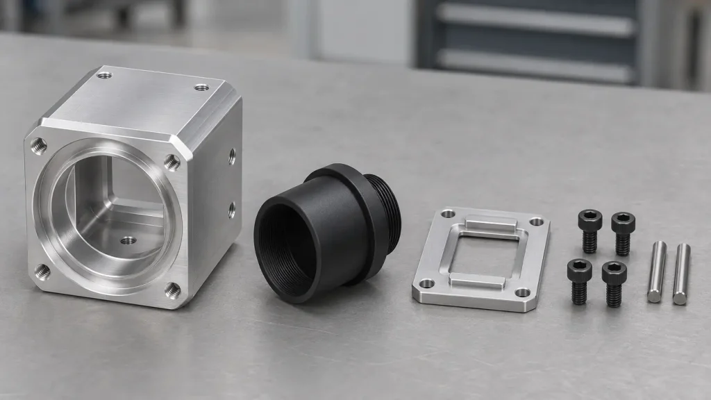
A housing may protect electronics, conduct heat and support a lens without directly locating the image sensor. Another design may establish the entire mechanical chain between the lens mount and sensor carrier. Identifying that difference comes before allocating tolerances.
Focus concerns where the image forms relative to the sensor. Tilt describes an angular relationship, while decenter describes lateral displacement. These errors can interact, but their drawing controls and correction methods differ. Uneven sharpness across an image also warrants checking the lens, target geometry and test conditions before assigning the cause to housing tilt.
Separate features that locate components from those that retain them. A shoulder can establish a seating position while a retaining ring maintains contact. Clearance screws may provide clamping without establishing repeatable lateral location.
The RFQ should state whether the housing arrives ready for fixed assembly or supports later alignment. An adjustable design needs controlled movement and a reliable locking method. A fixed design needs an allocation covering the mating lens assembly and sensor package, including their relationship to the mechanical references available for inspection.
Machining Camera Module Housings: Build the Datum Chain
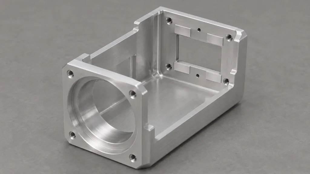
Start with the lens supplier’s mounting definition and the sensor supplier’s package drawing. A lens barrel’s outside cylinder does not automatically represent its optical axis. Likewise, the back of a PCB does not automatically establish the position or orientation of the active imaging plane.
Connect those supplier references through the housing’s functional surfaces. The drawing should make that chain inspectable without relying on cosmetic geometry.
| Housing feature | Contribution to alignment | Relevant inspection question |
|---|---|---|
| Lens seating shoulder | Establishes axial seating | Where is the seat relative to the sensor support reference? |
| Locating bore or pilot | Establishes mechanical lateral location | Are size, form and axis relationships controlled? |
| Sensor mounting pads | Support the carrier or board | Do the pads establish the intended seating plane? |
| Locating pins or shoulders | Support repeatable lateral positioning | How do their positions relate to the lens reference? |
| Retention interfaces | Maintain contact after fastening | Does tightening preserve the intended seating condition? |
Flatness alone cannot define a pad plane’s orientation relative to a lens reference. Select the necessary geometric controls under the drawing’s governing tolerancing system, and identify how inspection will establish the datums.
Pro Tip: Reference the sensor’s active-plane location through its supplier-defined package datums. PCB flatness alone does not define the imaging plane.
Allocate the Focus and Angular Error Budgets
The focus tolerance stack can include the housing shoulder position, lens mounting register, spacer thickness and sensor-package offset. Adhesive thickness or carrier seating may add further contributions. Use a signed dimensional chain so that each variation has a defined direction and reference.
A lens’s focal length cannot substitute for the mechanical distance required between its mounting reference and the sensor. Obtain the interface definition for the intended optical configuration, object distance and focus setting.
Angular sensitivity deserves a separate calculation. For an illustrative rigid seating plane, a height difference of 10 µm across a 20 mm support span gives:
θ ≈ Δh ÷ L = 0.010 ÷ 20 = 0.0005 radians ≈ 0.029°.
This is a geometric illustration, rather than a recommended camera tolerance or a BOONA capability claim. Board bending and package geometry can change the actual sensor-plane relationship.
Allocate manufacturing, assembly and operating effects separately. An adjustment mechanism can compensate for some initial variation, provided sufficient travel remains. It does not eliminate movement from locking, thermal gradients or later disassembly. Reserve appropriate allowance for those stages before assigning the housing its share of the budget.
Machining Camera Module Housings: Materials and Sequencing
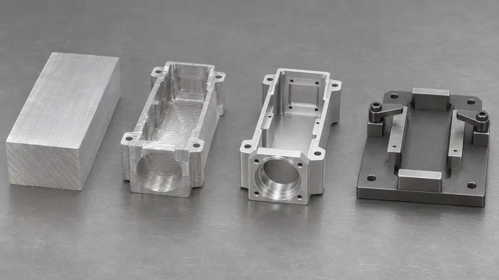
Material selection should consider the complete lens-to-sensor structure. Aluminum offers useful machining and heat-transfer characteristics, but its suitability depends on stiffness, temperature distribution and the expansion of the mating parts. A heat path that cools electronics can also introduce a gradient through the alignment structure.
For aluminum CNC machining, specify the alloy, temper and relevant stock condition. Thermal stability also depends on geometry, constraints and residual stress; selecting a stronger alloy alone does not settle those questions.
For a BOONA housing quotation, we recommend reviewing the order of pocket machining and datum finishing together. Removing substantial material after finishing a thin sensor support can change its released shape. The process plan should identify when to remove bulk material and when to finish the surfaces carrying the alignment relationship.
Where access allows, finishing related seats in a common setup can reduce datum transfers. Where separate setups are necessary, define the transfer features and inspection approach explicitly.
Clamping requires similar attention. A fixture that pulls a flexible housing flat may conceal its free-state distortion. Agree whether acceptance applies to the released component, a defined restrained condition, or both, and reproduce the relevant support locations during inspection.
Design Adjustment, Retention, and Assembly Access
Choose the alignment strategy before finalizing the housing. Fixed seats suit assemblies whose component variation fits the optical budget. Axial shims provide discrete spacing correction. Threads permit continuous axial adjustment but require control of lateral play and the locking operation. Active alignment uses optical feedback to select the final relative position.
A 2026 study of sequential camera-module active alignment, Section 4.3, Table 5, reports mean absolute sensor-tilt estimation errors of 0.023° and 0.006° about its respective axes across four prescribed poses of one offline-validation module. These are method-validation results, rather than housing tolerances or post-cure residual angles. This was not a BOONA project and does not demonstrate BOONA capability. The engineering inference is that alignment measurement has its own uncertainty allocation.
Provide access for adjustment tools, fasteners and inspection without disturbing the optical interfaces. Check that screws clamp the intended surfaces before reaching thread runout or bottoming.
Define how alignment survives locking. Tightening can shift a carrier through clearance or distort its support. Adhesive bonding requires control of the bond line and cure-related movement. Include cable routing and thermal-interface pressure when evaluating the final assembled condition.
Specify Finishing, Masking, and Cleanliness
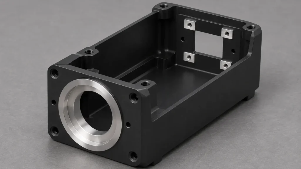
Finish requirements belong on the interface drawing before machining begins. Coating can change bore size, seating height and thread behavior. State whether critical dimensions apply before or after finishing, and show the surfaces that require masking.
For BOONA DFM review, our recommendation is to keep masking boundaries away from seating contact bands wherever practical. A coating edge or residue beneath a carrier can introduce a local stand-off even when the surrounding surface meets its drawing requirement. Define the contact region, rather than leaving the finisher to infer it from a general masking note.
Distinguish locating surfaces from bonding surfaces and cosmetic areas. Each can need a different preparation or protection method. Any finishing repair should preserve the specified final interface geometry.
A visually black interior also needs application-specific evaluation if stray light matters. Appearance alone does not establish reflectance over the camera’s operating wavelength range.
Specify cleaning and packaging around the optical assembly process. Blind pockets, intersecting holes and insert installation can retain chips or release debris. Define acceptable residues and handling requirements; reserve outgassing or other specialized requirements for applications that actually need them.
Separate Housing Inspection from Optical Validation
Housing acceptance should establish the functional datum relationships in the specified final condition. Check accessible seat geometry directly and agree an inspection method for recessed pads or bores. Include relevant inserts and finishes before final acceptance where they affect the interface.
Assembly checks then address seating, tightening movement and retention. Optical validation evaluates focus and image quality using defined targets, illumination and focus settings. A dimensional report cannot independently establish these results.
Application Example: A Hyperspectral Imaging Housing
A 2025 hyperspectral-camera study provides a useful scientific-imaging example. Section 5, Figure 9b, identifies a housing measuring 55 × 50 × 175 mm, excluding the front lens and CMOS camera. Section 5 describes components located in machined slots and a CNC-machined aluminum structure.
The researchers separated assembly variation from later stability effects involving vibration and locking in Section 4.4. They then evaluated the assembled optical system: Section 6.1, Figure 12, middle panel, reports a measured spectral-line full width at half maximum (FWHM) of 1.54 nm at 546 nm.
The application requires spectral and spatial fidelity. Section 6.2 also assesses optical distortions without attributing them to housing machining errors. The measured spectral result belongs to the complete instrument; it is neither a housing machining tolerance nor proof of environmental durability. This was not a BOONA project and does not demonstrate BOONA capability. Our engineering inference is to define component-location, retention and optical-performance acceptance separately.
Build an RFQ Around Focus and Tilt Requirements
An RFQ becomes easier to compare when the supplier can identify which surfaces carry the optical budget. Include the assembly drawing alongside the housing model, with controlled revisions for the lens mount and sensor interface.
Use the following information to connect design intent to the quotation:
- Identify the lens mounting reference and the sensor active-plane relationship available from their suppliers.
- Define housing datums, critical dimensions and the required final inspection condition.
- State material, stock condition and any restrictions on substitutions.
- Describe adjustment travel, shims, retention and locking access.
- Mark coating boundaries, protected contacts and bonding surfaces.
- Assign responsibility for dimensional reports, assembled alignment and optical tests.
- Specify cleanliness, protective packaging and the development or production quantity.
Review cost against each requirement’s purpose. Deep internal seats may need special tooling or inspection access. Thin walls can increase fixturing effort. Tightening an external cover dimension offers little value if the uncontrolled sensor support remains the dominant contributor.
Also define service expectations. If replacing a sensor carrier requires fresh optical alignment, the design and quotation should accommodate that operation. Where repeatable replacement is necessary, locating interfaces and retention must support it, with validation of the complete replacement procedure.
FAQs
What housing features control camera focus?
The lens seat, mounting register, spacers and sensor supports contribute to axial positioning. Their effect depends on the lens and sensor interface definitions. Housing depth by itself does not establish the final focus position.
What causes tilt between a lens and image sensor?
Possible contributors include pad-height differences, package orientation, board deformation and uneven seating. Fastening or adhesive locking can add movement. Optical testing should distinguish these effects from target tilt and lens-related image variation.
Can tighter CNC tolerances eliminate active alignment?
They can reduce mechanical variation, but the decision depends on the complete optical and assembly budget. Lens variation, sensor-package offsets and locking movement may still require adjustment or optical feedback during assembly.
Can the sensor PCB serve as the imaging-plane datum?
Only through a validated relationship to the active sensor plane. The PCB surface alone does not establish that plane. Use supplier package information and account for mounting support and board deformation.
How does anodizing affect lens and sensor interfaces?
It changes the finished geometry of coated surfaces. Specify masking and the dimensional inspection state, especially for bores and seating pads. Avoid placing an uncontrolled coating boundary underneath a functional contact.
Does dimensional inspection prove camera image quality?
It verifies the specified component geometry. Focus, field-dependent image quality and alignment retention require appropriate assembly and optical checks. Define the acceptance criteria and responsible party for each stage in the order.
Conclusion: Control the Interfaces and the Validation Handoff
Machining Camera Module Housings successfully requires a clear chain from the lens reference to the active imaging plane. Give the axial and angular budgets separate attention, then carry them through machining, finishing and retention.
Procurement should also establish what the delivered evidence proves. The housing report covers specified component geometry. Assembly checks address seating and locking. Optical measurements determine whether the complete camera delivers the required imaging performance. Keeping those responsibilities explicit makes quotations more comparable and avoids assigning system-level results to a supplied component.
Send BOONA your housing CAD, controlled drawings and mating-interface requirements for a CNC machining review and quotation. There is no minimum order quantity, and a free DFM review helps identify machining, finishing and inspection questions before the production requirements are finalized.