
The “7” in H7 identifies a tolerance grade. Reading it as a fixed micrometre allowance sends the wrong limits into manufacturing and inspection. Before anyone programs the bore or sets a gauge, the drawing needs a nominal size and an unambiguous tolerance class.
An H7 bore and g6 shaft pairing places the hole’s lower size limit at nominal and the shaft’s size interval below nominal. For matching nominal sizes, this produces a clearance fit. Its numerical limits depend on the applicable size range.
Read the feature, look up its deviations, calculate the permitted diameters, and evaluate the limiting clearances. Then check the separate requirements for geometry, finishing, and inspection.
H7 Bore and g6 Shaft: Decode Size, Letter, and Grade
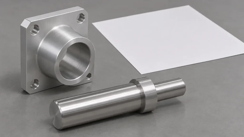
What the nominal diameter tells you
Nominal size provides the reference from which deviations are applied. It is neither a measured result nor an instruction to machine exactly at that value.
In an illustrative callout of ⌀25 H7, the diameter symbol identifies a cylindrical size. The nominal value and tolerance class together establish its permitted size interval. A different nominal diameter can require different numerical deviations even when H7 remains unchanged.
What H7 means on a bore
Uppercase letters identify hole tolerance classes. H positions the lower hole limit at nominal size; the permitted interval extends above it. The numeral identifies standard tolerance grade IT7.
The grade determines the interval’s width within the relevant size range. It does not specify surface roughness, a particular cutting tool, or a universal dimensional allowance.
What g6 means on a shaft
Lowercase g identifies a shaft tolerance zone below nominal size. Its upper limit is already smaller than nominal, and IT6 establishes the zone’s width.
Capitalization therefore carries engineering meaning. Preserve it when transferring callouts into quotations, process sheets, and inspection software.
Read Component and Assembly Drawings Together
Individual and combined callouts
An assembly drawing can show H7/g6 as the intended pairing. Each component drawing still needs to identify its own controlled feature.
Check where the dimension applies. A chamfer, relieved section, or adjacent diameter should not silently become part of the functional mating land. Where explicit limits and coded tolerances disagree, obtain an engineering decision.
For a BOONA drawing review, our recommendation is to carry the resolved limits into a revision-controlled process sheet. A machine offset cannot resolve conflicting design requirements.
A documented calibration-artifact example
A 2021 DTU dissertation describing an X-ray CT reference artifact provides an unusual application. Chapter 5, Section 5.2.4, “Fits of external and internal inserts,” printed pages 78–79, specifies g6 on nominal 4 mm insert diameters and H7 on matching holes. It also applies the pairing to nominal 4 mm insert widths and slots.
The inserts needed removal, repositioning, and material exchange. Separate assembly hardware provided retention. This is a documented research design, not a BOONA project or evidence of BOONA capability.
Our engineering inference is that the fit code must travel with its feature and assembly purpose. The same designation can appear on different feature types; it does not explain how an assembly retains them.
Find the Correct Limits in ISO 286
Understand the roles of the two parts
ISO 286-1:2010 establishes the code system’s principles and terminology. ISO 286-2:2010 provides tabulated tolerance classes and limit deviations.
ISO lists both editions as current following confirmation in 2026. Their published 2013 corrigenda also require attention. The confirmation year does not rename either document as a new technical edition.
Select the correct size interval
Read the table headings literally, including “above” and “up to and including.” A nominal size exactly at a boundary belongs to the interval specified by those words.
Confirm the hole or shaft table, the tolerance class, and the units. Do not transfer an interval from a neighboring letter or assume every table uses identical subdivisions.
Convert deviations into dimensional limits
A deviation is a signed distance from nominal size. A limit is the resulting permitted dimension.
Add the upper deviation to nominal size for the maximum limit. Add the lower deviation for the minimum limit. Preserve negative signs and convert units consistently.
Keep the lookup source and size interval with the calculation so another reviewer can reconstruct it.
H7 Bore and g6 Shaft: Calculate the Clearance
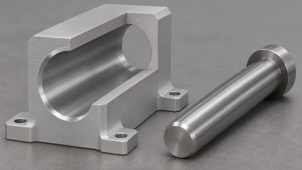
Build the dimensional limits
Use an illustrative 25 mm nominal diameter. The Government of India’s machine-tool training text, revised in 2022, Table 1, printed page 110, row “Over 24 up to 30,” supplies the deviations below. Printed page 109 clarifies the micrometre units. This is a historical BIS teaching chart; the drawing’s controlled ISO reference governs contractual acceptance.
| Feature | Nominal size | Lower deviation | Upper deviation | Minimum size | Maximum size |
|---|---|---|---|---|---|
| H7 bore | 25 mm | 0 µm | +21 µm | 25.000 mm | 25.021 mm |
| g6 shaft | 25 mm | −20 µm | −7 µm | 24.980 mm | 24.993 mm |
The limits follow by adding the stated deviations to the chosen nominal diameter. They are design limits for this example, not BOONA capability figures.
Calculate the limiting combinations
Minimum clearance = smallest bore − largest shaft
25.000 − 24.993 = 0.007 mm, or 7 µm.
Maximum clearance = largest bore − smallest shaft
25.021 − 24.980 = 0.041 mm, or 41 µm.
These are calculated diametrical clearances. For ideal coaxial circular features, the corresponding radial gap is half the diametrical value.
Interpret the result correctly
The calculation describes the permitted size combinations. It does not establish shaft alignment, friction, lubrication requirements, or operating behavior.
Use the actual nominal diameter whenever the design changes. Copying this clearance range onto another size without a new lookup can produce an incorrect requirement. Keep form, surface condition, and the intended inspection state in the same review.
Recognize What the Fit Code Leaves Unspecified
Form and geometric relationships
The code alone does not define every geometric relationship needed for function. Review form, orientation, and location requirements alongside the specified size operator. Consider the complete engagement length rather than relying on an entrance diameter.
A 2023 study of precision holes in 42CrMo4 QT steel illustrates why machining details still matter. Section 3, Figure 8a and its accompanying discussion report mean cylindricity after reaming of 6.578 µm for drilling strategy DT0 and 4.307 µm for DT2.
These are form measurements from the tested machining routes. They are neither clearance values nor proof that every specimen met its size limits. This was independent university research, not a BOONA project or evidence of BOONA capability. Our engineering inference is to verify required form separately rather than treating a finishing operation as sufficient evidence.
Surface texture and edge condition
Surface texture influences contact, while burrs and damaged edges can interfere with insertion. Define suitable lead-ins and permissible edge breaks without eroding the functional land.
Finishing and operating conditions
Coatings can change shaft and bore dimensions. State whether the drawing’s limits apply after finishing and identify any masking boundaries.
Material combinations and temperature changes can alter operating clearance. The supplied-part acceptance condition and the service requirement need separate consideration; a universal compensation value cannot replace that assessment.
Connect the Callout to Machining and Inspection
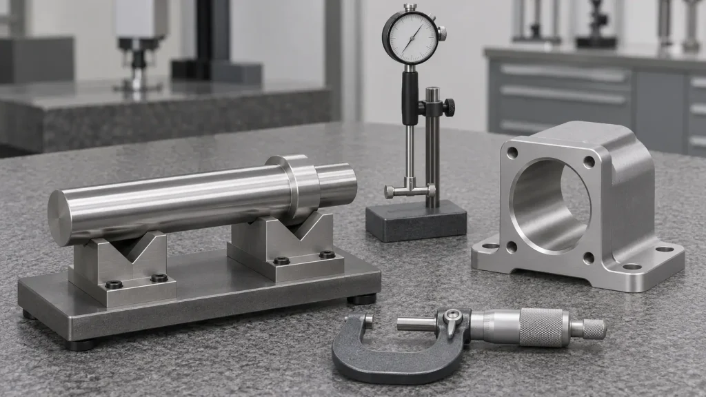
Select the process around the feature
Boring, reaming, turning, or grinding may suit the component. H7 does not mandate reaming, and g6 does not prescribe grinding.
Geometry, material condition, and required form influence the route. Discuss cylindrical features through BOONA CNC turning services while reviewing bore operations and datum transfer as part of the complete process.
Our BOONA machining-review recommendation is to resolve interrupted bore features before selecting the final sizing sequence. A cross-passage can create an edge that needs deburring after the bore has been finished. Agree which operation removes that burr and how the mating surface will be protected.
Plan inspection coverage
A 2023 roundness-measurement study, Section 4, Figure 11 and its accompanying discussion, reports differences exceeding 12% when profiles were reduced to eight sampled points. Its reference profiles contained 3,600 points, as described in Section 2.2.2.
The experiment used intentionally deformed teaching specimens. It establishes neither a production rejection rate nor a universal sampling requirement. This was not a BOONA project and does not demonstrate BOONA capability. Our engineering inference is to validate sampling against the shape features that inspection must detect.
Define the delivered condition
Document inspection support, temperature condition, and whether coating is complete. Select suitable gauges or variable measurements, then agree the conformity decision rule and relevant uncertainty. A display’s resolution alone cannot establish measurement capability.
Use a Drawing-to-Inspection Checklist
A controlled handoff makes the calculation useful beyond the person who performed it. The framework below separates the decisions that otherwise become buried in a tolerance label.
| Review stage | Question to resolve | Required output |
|---|---|---|
| Feature identification | Which land carries the callout? | Defined feature and nominal size |
| Code interpretation | What do the letter and grade specify? | Correct tolerance class |
| Table lookup | Which interval and deviations apply? | Traceable dimensional limits |
| Fit calculation | What are the limiting size combinations? | Minimum and maximum clearance |
| Manufacturing handoff | What finishing and inspection conditions apply? | Agreed acceptance requirements |
For an RFQ, attach the controlled component drawings and relevant mating requirements. Add material condition, functional engagement, and coating coverage. Identify the inspection records needed for acceptance.
Changing a bore or shaft diameter should trigger a new lookup, even when the tolerance letters remain unchanged. Changes to finishing or assembly conditions also deserve review.
Pro Tip: Record the applicable size interval alongside the calculated limits. This makes a boundary-range lookup error easier to catch before machining begins.
Keep the calculation tied to its drawing revision. If the purchasing specification repeats numerical limits, update that document together with the drawing rather than allowing separate versions of the requirement to circulate.
FAQs
What does H7 mean on a bore drawing?
H identifies the hole tolerance zone with its lower size limit at nominal. The numeral specifies IT7. Numerical limits also require the nominal size and correct table interval.
What does g6 mean on a shaft drawing?
Lowercase g identifies a shaft zone below nominal size, and the numeral specifies IT6. Both deviations are needed to calculate permitted diameters. Preserve the lowercase letter when transferring the requirement.
Is H7/g6 a clearance fit?
For matching nominal sizes, the H hole starts at nominal while the g shaft lies below it. Calculate minimum and maximum clearance for the actual diameter. The pairing does not independently establish alignment, friction, or suitability for a particular bearing.
Does H7 mean seven micrometres?
The numeral identifies a tolerance grade. Its dimensional width depends on nominal size. Use the applicable ISO table to determine that width rather than interpreting the grade number as a unit-bearing allowance.
Does an H7 bore have to be reamed?
The code specifies a dimensional requirement. Select the process around material, access, and geometry. Required form and surface texture can influence that choice.
Do H7 and g6 apply before or after coating?
The manufacturing package should state that explicitly. Where a finished mating fit is required, define final limits and coating boundaries. Resolve an ambiguous finishing condition before machining, and inspect the agreed delivered state.
Conclusion: Read the Complete Requirement
Reading an H7 bore and g6 shaft correctly requires the nominal size, letter case, tolerance grade, and applicable size interval. Convert deviations into component limits, then calculate the extreme clearance combinations.
The remaining drawing requirements determine how those dimensions support the assembly. Carry material condition and finishing instructions into the process plan, and select an inspection strategy that can verify the required geometry.
A useful handoff lets purchasing, machining, and inspection work from the same controlled limits.
Send BOONA your controlled drawings, mating-part requirements, and finishing specification for a CNC machining review. We offer no minimum order quantity and a free DFM review to help resolve tolerance interpretation, manufacturing access, and inspection scope before you order.