
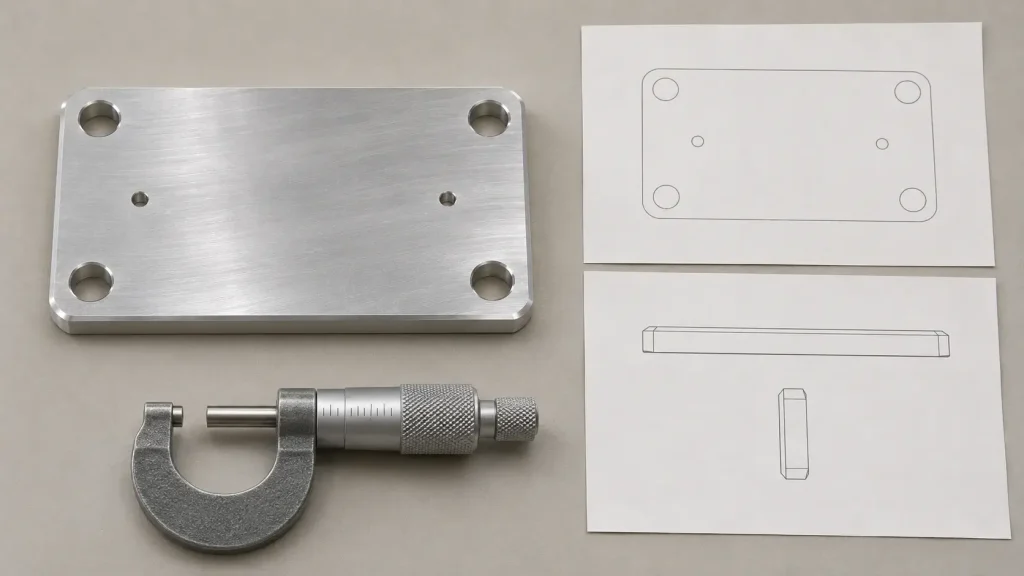
A buyer sends out a repeat order for a milled mounting plate. The CAD model is unchanged. On the new drawing, however, the title block has changed from ISO 2768-mK to ISO 2768-fH. One supplier adds a finishing operation. Another quotes the old process. The buyer needs to know which requirements changed before comparing those prices.
For ISO 2768-mK vs -fH, read the letters independently. The lowercase letter selects the dimensional class from legacy Part 1: m for medium and f for fine. The uppercase letter selects the geometrical class from legacy Part 2: K or H. In the worked example below, the change tightens the plate width and face flatness, leaves a chamfer limit unchanged, and still leaves hole-pattern position to an individual callout where the design requires it.
The practical starting point is the released drawing. Identify the governing edition, then check each feature for an individual requirement before using a general tolerance table. That gives procurement and inspection the same basis for evaluating the revision.
ISO 2768-mK vs -fH: Decode the Two Letters
Lowercase m and f for dimensional tolerances
The first letter covers applicable linear and angular dimensions without an individual tolerance under ISO 2768-1:1989. For a plate width, start with the nominal dimension and find its range in Table 1. For a dimensioned broken-edge chamfer height or external radius, use Table 2. For an applicable angular dimension, Table 3 indexes the tolerance by the length of the shorter side forming the angle. Clause 1 also excludes bracketed auxiliary dimensions and boxed theoretically exact dimensions.
Uppercase K and H for geometrical tolerances
The second letter selects the class for general geometrical tolerances under ISO 2768-2:1989. Clauses 2 and 5 cover characteristics such as flatness, perpendicularity and circular runout, each with its own application rule. Clause 6.1 gives ISO 2768-mK as the combined title-block example. The full ISO 2768-fH designation follows the same order.
An implied right angle is an easy place to use the wrong table. If the drawing shows two sides meeting squarely without an angular dimension and the combined note applies, clause 6.1 directs the reader to general perpendicularity in Part 2. Clause 5.2.3 and Table 2 use the shorter side to select the limit and the longer side as the datum, with either side available when their nominal lengths are equal. That default datum may differ from the surface that locates the part in the assembly.
Compare ISO 2768-mK vs -fH on One Drawing
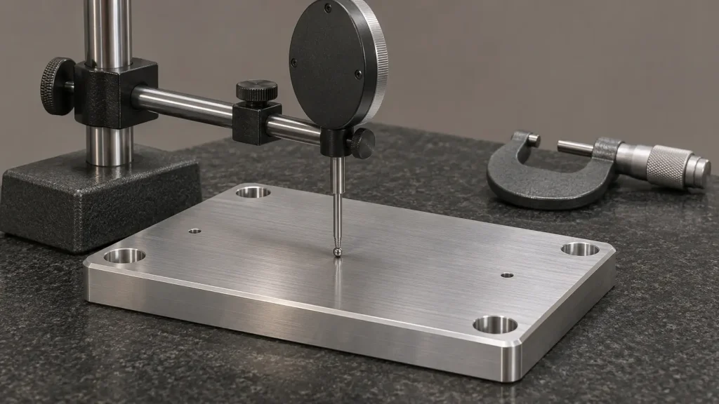
Consider a hypothetical mounting plate whose drawing invokes the legacy 1989 editions. Its outside width is dimensioned, one broad face needs a flatness check, and a small chamfer breaks an exposed edge. Assume the drawing gives none of those characteristics an individual tolerance. A pair of dowel holes locates a mating component, so the review also asks how to control that pattern.
| Feature or requirement | mK |
fH |
Exact legacy lookup |
|---|---|---|---|
| 50 mm outside width | ±0.30 mm | ±0.15 mm | Part 1, Table 1, over 30 through 120 mm |
| Flatness of a rectangular face with a 50 mm longer side | 0.20 mm | 0.10 mm | Part 2, clause 5.1.1 and Table 1, over 30 through 100 mm |
| 1 mm broken-edge chamfer height | ±0.20 mm | ±0.20 mm | Part 1, Table 2, 0.5 through 3 mm |
| Dowel-hole pattern position relative to datums | Individual callout if required | Individual callout if required | Part 2, clause 2 excludes positional tolerances |
For the width, subtract and add the Part 1, Table 1 deviations to the nominal dimension. The calculated interval is 49.70–50.30 mm under mK and 49.85–50.15 mm under fH. The two intervals govern the same width on otherwise identical drawings.
For flatness, the table value is the total separation between the two parallel planes that bound the surface. Writing ±0.10 mm would misstate the zone. Notice the different lookup ranges in the first two rows. The nominal width and the longer side of the face happen to be the same in this example, yet each characteristic has its own table and range. Use that distinction when transferring limits to a first-article report.
Identify Features That Need Their Own Callouts
An individual tolerance governs the characteristic it addresses. A bore diameter with its own limits takes those size limits. Review the bore’s form and relationship to other features separately. A dowel can fit into each hole individually while the pair still needs a positional requirement tied to the surfaces that locate the mating component.
The legacy dimensional class can apply to eligible coordinate dimensions with no individual tolerance. A datum-related position callout defines a different requirement. Use it where the pattern’s relationship to the assembly matters, and show the functional datum references. For a sealing face, decide whether the drawing needs a dedicated flatness limit, a surface texture requirement, or both. For a bearing seat, define the required fit and any additional form control that the application needs.
Application example: A particle detector’s alignment reference
Section 3.2.2 of the 2024 LHCb VELO upgrade paper describes a machined aluminum detector module foot with a precision-drilled hole for mounting and alignment. Section 5.2.1 explains how the team used that hole as a reference for optical measurements of the attached sensor tiles.
Section 7.2.2, alongside Figure 56, reports a mean tile-center offset of 21 µm with a standard deviation of 10 µm across installed modules. The team also detected drift in one tile’s placement during production and corrected it by adjusting the positioning system’s alignment constants. The figures describe assembled tile positions. The research team worked independently of BOONA, and its results provide no evidence of BOONA capability. The engineering inference for a machined locator is to identify the physical reference and specify the positional relationship that the inspection plan must verify.
Check the Standard Edition Before Updating a Legacy Drawing
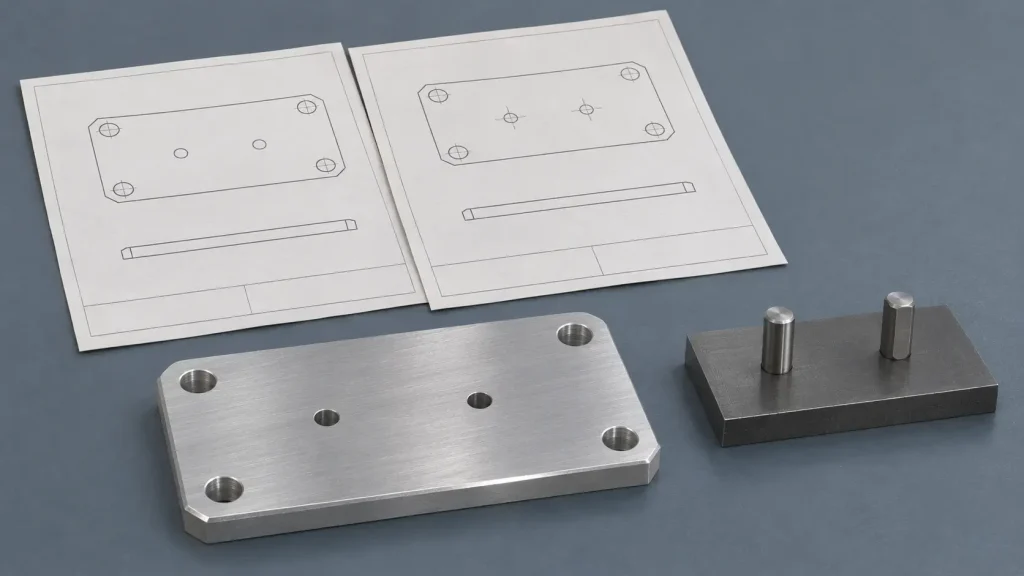
Confirm the governing edition on a repeat order
Both parts that define the legacy code are withdrawn. The life-cycle record for ISO 2768:2026, stage 60.60, lists November 9, 2026 as the publication date of the current edition and identifies Part 1:1989 as the withdrawn predecessor. Clause 1 limits the new edition to general specifications for linear and angular sizes, with dimensional distances outside its scope. Its Foreword also identifies the removal of the former broken-edge tolerance limits.
The ISO catalogue entry for ISO 22081:2021 lists Part 2:1989 as the withdrawn predecessor and records confirmation of the current edition at stage 90.93. ISO 22081 gives rules for stating and interpreting general geometrical and size specifications. A drawing migration requires defining the applicable features, values and datum references for the new specification.
Audit coverage before changing the note
Review the released drawing, referenced specifications and purchase documents together. If they establish the legacy requirements for the order, use that basis for the quote and inspection plan. Ask the drawing owner to resolve an undated or conflicting reference before accepting it as a manufacturing instruction.
For a revision, compare feature coverage before and after the change. Start with hole-center distances, broken edges and surfaces with an inherited geometrical requirement. A plate’s outside width and the distance between two hole centers can both appear as linear dimensions on a drawing. The distinction between size and distance determines how they must be specified under the current edition. Record how the revised drawing will control each required characteristic and update the inspection plan with it.
Turn the Title-Block Note Into an RFQ Checklist
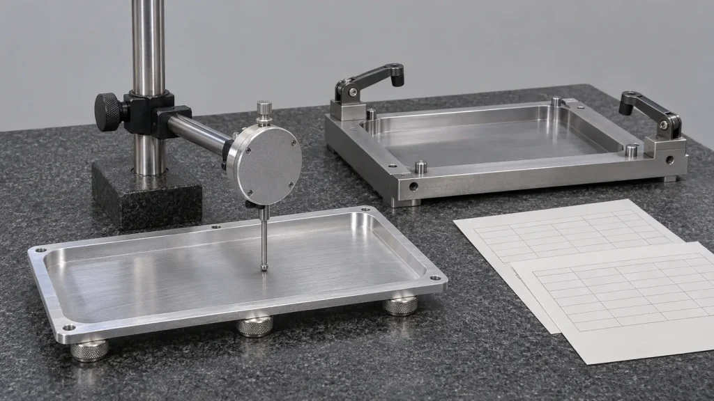
Ask suppliers to price the same drawing revision and identify the limits that drive machining or inspection. Use three groups in the quote review:
- Limits that change. Record the old and new values, their table ranges, and the operation or check the supplier would change. For the example plate, compare the width measurement and the face flatness measurement as separate checks.
- Limits that stay the same. Record unchanged table values and retain the drawing’s individual callouts. The chamfer in the worked example belongs here.
- Requirements that need an individual callout. Ask engineering to resolve functionally necessary controls that the note leaves open. Give each one a feature identifier so the drawing, quote and inspection report refer to the same surface or pattern.
In our CNC milling work at BOONA, we separate bulk roughing from finishing on distortion-sensitive parts and use low-force workholding where appropriate. Agree how to support a thin plate during free-state inspection so the inspection fixture does not flatten the very surface you need to evaluate. For an anodized bore that must meet a finished size, we work backward from the final limits and account for net coating buildup when setting the machining target. The RFQ should specify the finished condition and any masking boundaries.
In Section 3.2, Table 2, a 2026 study of thin-wall milling and flatness reports bottom-face flatness deviations of 0.0612 mm for the outside toolpath and 0.0457 mm for the optimized toolpath on the tested thin-walled frames. The researchers measured after removing the parts from the machine table and allowing them to age. These results apply to the experimental parts and process. The study was conducted independently of BOONA and provides no evidence of BOONA capability. The engineering inference is that a tighter flatness requirement can affect how a supplier finishes the part and verifies it after machining.
Pro Tip: Put the checked surface, table range and inspection condition on the same line of the first-article plan. A bare flatness value leaves the next reviewer guessing which surface and support condition it describes.
FAQs
What do mK and fH mean on an engineering drawing?
They combine two classes under the legacy ISO 2768 convention. The first letter selects the dimensional class for applicable linear and angular dimensions. The second letter selects the general geometrical class for the characteristics covered by Part 2.
Is fH tighter than mK for every feature?
The result depends on the characteristic and its lookup range. In the worked example, the width and flatness limits tighten while the broken-edge chamfer keeps the same permissible deviation. An individual callout continues to govern the characteristic it specifies.
What does a drawing note of ISO 2768-m cover?
Under the legacy convention, it invokes Part 1’s medium class for applicable dimensions without individual tolerances. The single lowercase letter supplies a dimensional class. Look elsewhere on the drawing or in a referenced specification for any general geometrical requirements.
Does ISO 2768-mK control hole position?
Legacy Part 2, clause 2 excludes positional tolerances. Applicable coordinate dimensions can still have general dimensional limits. Where a hole pattern must locate a mating component relative to datums, specify the positional requirement that reflects that function.
Can a repeat order still use a drawing that references the 1989 editions?
Yes, if the approved drawing and purchasing documents retain those editions as the governing requirements. Confirm the revision and edition when placing the order. Refer conflicting documents to the drawing owner for resolution.
What needs review when migrating to ISO 2768:2026 and ISO 22081:2021?
Check the scope of each general specification, the selected limits and the relevant datum references. Pay particular attention to legacy dimensions for distances and broken edges. Update the drawing and inspection plan together so the new specification has a clear acceptance method.
Conclusion: Specify the Features That Drive Acceptance
The useful comparison in ISO 2768-mK vs -fH is the change in requirements for each feature. Start with the governing edition and preserve individual callouts. Then look up the remaining general limits using the correct characteristic and range. A short review of the width, flatness, chamfer and dowel pattern can show where a revised note adds inspection work and where it leaves a design decision open.
For a legacy drawing revision, record the agreed limits and the condition in which each feature will be measured. If a requirement depends on how the part seats, where it locates or what happens after finishing, put that information in the manufacturing package before quotes go out.
Send your CAD and controlled drawing to BOONA precision machining team. Include the mating or finished surfaces that drive acceptance. There is no minimum order quantity, and a free DFM review can help clarify the machining and inspection scope before you place an order.