
A thermostat enclosure can pass dimensional inspection and still behave badly once the electronics go inside. The display may sit square in the bezel, yet the temperature sensor reads warmer than the room because a regulator is heating the air behind it. Move to an aluminum front frame and another issue can appear: the antenna now operates beside a large piece of metal.
That is the real challenge in machining smart home device housings. The enclosure is part of the electronic system. Its material, internal clearances, mounting points, vents, and mating surfaces all influence how the finished device works.
For a prototype team, CNC machining provides a useful checkpoint before production tooling. Engineers can assemble real PCBs, displays, sensors, antennas, buttons, and seals inside a housing made from the intended engineering material. Problems that looked harmless on-screen become much easier to judge on the bench.

What Smart Home Device Housings Can Be Machined?
There is no single geometry that defines a smart-home enclosure.
A thermostat typically has a display or dial on the front, a PCB close behind it, and one or more environmental sensors that need exposure to room air. Wall mounting also limits the space available behind the board.
A smart lock has a different set of constraints. The outer housing is handled every day and may contain a keypad, fingerprint reader, motor, battery compartment, and mechanical lock interface. Exterior parts also have to survive cosmetic wear.
Connected cameras bring optics into the tolerance chain. Lens position matters, but so do infrared emitters, microphones, thermal paths, seals, and the alignment between a PCB-mounted image sensor and the housing opening.
Smart speakers and hubs tend to be less mechanically exposed, yet their packaging can be crowded. Microphone openings, speaker cavities, antennas, connectors, and status lights all compete for space.
This variety is why an enclosure should be reviewed around the actual electronic architecture. A housing that works for a control hub may be a poor starting point for a thermostat or video doorbell, even when the outer dimensions are similar.
Why CNC Works for Machining Smart Home Device Housings
CNC machining is most valuable while the product architecture can still change.
A machined enclosure lets an engineering team test real mounting surfaces and mating interfaces without committing to a mold. PCB standoffs can be measured in an assembled product. A connector opening can be checked with the actual connector rather than a nominal CAD envelope. Threaded inserts, gasket paths, heat-transfer surfaces, and display openings can all be evaluated physically.
Design changes remain relatively straightforward at this stage. If a board revision moves a connector by 0.4 mm, the housing model can be updated before the next prototype run. A similar change after tooling may affect inserts, shutoffs, slides, or cavity steel.
CNC also gives teams access to production-relevant metals such as aluminum and to engineering plastics that are useful during functional evaluation.
The limitation is equally important. A machined plastic housing will not reproduce every behavior of an injection-molded part. Draft, resin flow, weld lines, molded-in stress, sink, and production snap-fit behavior require a separate molding review.
For that reason, we use a CNC enclosure to answer practical questions first: Does everything fit? Can the product be assembled without hand rework? Are the critical interfaces where the electronics team expects them to be?
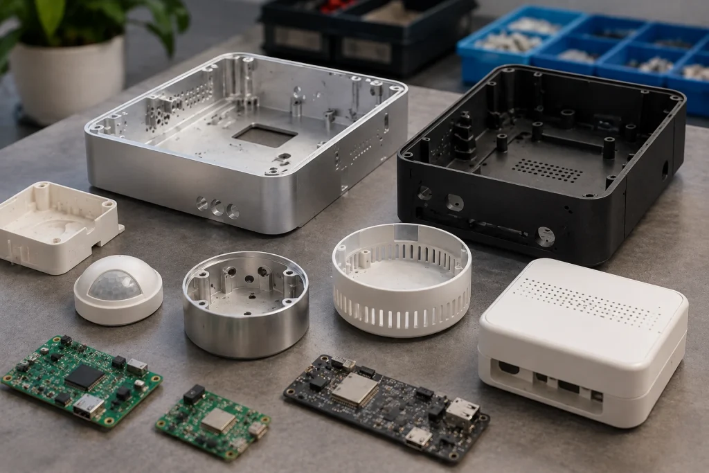
Material Choices for Machining Smart Home Device Housings
Material selection often exposes conflicts between industrial design and electronics.
| Material | Typical Use | Main Benefit | Design Concern |
|---|---|---|---|
| Aluminum 6061 | Frames, locks, hubs, premium housings | Good machinability and heat spreading | Metal must be considered around antennas |
| Aluminum 7075 | Highly loaded structural parts | Higher strength | Often unnecessary for cosmetic shells |
| ABS | General enclosure prototypes | Familiar electronics material | Machined behavior differs from molded ABS |
| Polycarbonate | Protective covers and housings | Toughness and impact resistance | Heat control matters during machining |
| PC/ABS | Consumer-electronics housings | Balanced mechanical properties | Prototype stock may differ from production grade |
| POM | Internal guides and moving features | Dimensional stability and low friction | Less common as the visible outer shell |
Aluminum 6061 is a practical choice when the housing doubles as a structural frame or heat spreader. It also supports durable threads and cosmetic finishes.
Plastic is often preferred around antennas because it avoids surrounding the RF system with a continuous conductive shell. It can also reduce weight and provide electrical insulation.
The decision should be made with the PCB and antenna layout visible. Selecting a metal housing first and asking the RF engineer to solve the resulting antenna problem later usually creates unnecessary constraints.
A hybrid structure can be more effective: metal where stiffness or heat spreading matters, and plastic where the antenna needs a suitable RF path.
Designing the Housing Around Wireless Connectivity
Wi-Fi, Bluetooth Low Energy, Thread, and similar wireless systems add a requirement that is easy to miss during mechanical review: the enclosure changes the electromagnetic environment around the antenna.
A metal wall close to an antenna can alter its behavior. The solution depends on the radio architecture and antenna design, so there is no universal clearance value that belongs on every smart-home drawing.
Mechanical engineers should ask for the antenna keep-out zone before fixing nearby bosses, fasteners, batteries, internal walls, or decorative metal parts. This is especially important when the industrial design uses an aluminum frame.
Testing also needs to represent the final assembly. A bare PCB on a bench tells the RF team very little about what happens after the board is enclosed beside a battery, display, cables, screws, and metal trim.
Plastic RF windows are one option. Moving the antenna into another region is another. Some designs split the metal structure rather than wrapping it continuously around the electronics.
These decisions are easier to make while the housing is still being prototyped. Once cosmetic geometry, PCB position, and tooling are frozen, even a small antenna relocation can spread changes across several parts.
Thermal Management and Sensor Placement
A smart-home device does not need a high-power processor to create a local thermal problem.
Voltage regulators, wireless modules, displays, cameras, LEDs, and charging circuits all release heat. In a small sealed enclosure, that heat can raise the temperature around nearby components.
This matters especially for thermostats and environmental sensors.
A 2025 peer-reviewed smart thermostat validation study in Energies tested a controller in a 4 m × 4 m × 2.85 m environmental chamber. After training on one week of indoor conditions, its predictive model achieved an RMSE of 0.082–0.116°C and at least 97% thermal comfort on the reported test days.
Those figures are not enclosure specifications, but they show how finely a thermostat control system can work with temperature data. A sensor that is consistently warmed by nearby electronics can therefore introduce an error source outside the control algorithm itself.
Aluminum can help when there is a deliberate thermal path. A machined internal contact area, thermal interface material, and outer housing can spread heat away from a component.
For plastic housings, component spacing and ventilation may matter more. A sealed outdoor device creates another tradeoff because the enclosure has fewer opportunities to exchange air.
Sensor location should be reviewed together with the thermal map, rather than added after the board layout is complete.
Small CNC Features That Create Large Assembly Problems
Many enclosure problems begin with features that look insignificant on a drawing.
Take PCB standoffs. Their XY positions may be correct, yet an incorrect height changes the vertical location of every board-mounted connector and switch.
A USB-C opening has the same problem. The visible gap around the connector depends on the enclosure, PCB locating system, screw clearance, connector placement, and board assembly. Drawing the opening tightly around nominal connector dimensions does not remove those other sources of variation.
Buttons add another stack. The switch sits on the PCB, while the visible button belongs to the housing. Travel and lateral clearance have to work together. Too much gap looks cheap; too little can cause rubbing or sticking.
Gasket grooves deserve even more care. Width and depth determine how the seal sits, while corner geometry affects whether the gasket can follow the path cleanly.
For optical products, the stakes can be higher. The lens opening may use the enclosure as a locating reference, so a cosmetic feature suddenly becomes part of the optical alignment system.
During DFM, we find it useful to ask what each feature actually does. Locating features, seals, fasteners, and clearance pockets should not all be treated as though they carry the same functional risk.
Tolerance Strategy for Machining Smart Home Device Housings
Tighter tolerances everywhere do not guarantee a better smart-home enclosure.
A better drawing starts by defining which relationships matter to the assembled product.
The PCB datum system is usually one of them. Display alignment may be another. Camera openings, connector positions, button actuators, gasket surfaces, and the seam between housing halves can also deserve tighter control.
An internal relief pocket that simply keeps clear of a component may have much more freedom.
Consider a board-mounted connector that appears low in the finished housing. Tightening the connector opening alone may not solve the problem. The board itself could be shifting inside screw clearance, the standoff height could vary, or the connector placement could be contributing to the stack.
The drawing should make the functional chain clear enough that the manufacturer knows which dimensions need attention.
Pro Tip: Establish functional datums before tightening tolerances. Control the dimensions that locate the PCB, sensor, display, connector, gasket, and mating halves. Give ordinary clearance features room to be ordinary clearance features.
That approach also makes inspection more useful. Instead of measuring dozens of dimensions to an unnecessarily severe requirement, quality control can focus on the interfaces that determine assembly and product function.
Surface Finishing Without Losing Functional Interfaces
The finish specification should be part of the enclosure drawing, not a cosmetic instruction added after machining.
For aluminum smart-home housings, bead blasting followed by anodizing is common where a uniform matte appearance is required. Brushing creates a directional surface. Polishing exposes a very different visual character and can make surface inconsistencies easier to see.
BOONA surface finishing options cover machining-compatible processes such as anodizing, bead blasting, brushing, polishing, painting, and other secondary finishes.
The functional drawing still needs to identify areas that should be protected. Threaded holes, grounding surfaces, electrical contact areas, closely controlled fits, and selected mating surfaces may need masking or process-specific treatment.
Plastic prototypes have different priorities. Sanding, polishing, or painting may help a design team judge appearance, but a machined surface should not be used as an exact prediction of a future molded texture.
For appearance-sensitive products, finish samples are useful before a larger prototype build. A CAD rendering cannot show how bead blast hides tool marks, how two anodized parts match under room light, or how a painted plastic component looks beside anodized aluminum.
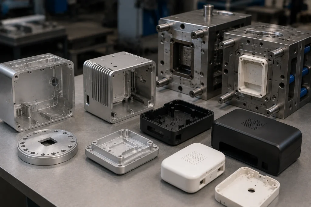
Moving From CNC Prototype to Injection-Molded Housing
A good CNC prototype proves the product architecture. It does not automatically prove that the same CAD is ready for molding.
Machining tolerates geometry that a mold may dislike. Deep pockets can be milled directly. Vertical walls do not need draft. Thick bosses can remain solid if their mass does not create another machining problem.
Injection molding changes those assumptions.
The design now needs suitable draft, wall-thickness transitions, ribs, cored bosses, parting strategy, gate placement, ejector access, and consideration of sink and weld lines. Snap features also need to be designed around the production resin and mold-release direction.
This transition is a useful point to review injection mold tooling separately from the CNC prototype.
Engineers do not have to redesign the entire product from zero. The CNC stage has already answered valuable questions about electronics packaging, ergonomics, connector access, and external proportions.
The next task is to preserve those validated relationships while changing the part so the production process can make it reliably.
Real-World Example: A Mobile IoT Air-Quality Monitor
A useful enclosure example comes from public transport rather than the smart-home industry.
A 2025 Sensors study of a mobile IoT air-quality monitoring system described a compact device used to monitor in-cabin conditions in Almaty. The unit combined environmental sensors, particulate sensing, gas sensing, Wi-Fi communication, ventilation openings, and active airflow.
The study reported 91.25% classification accuracy for its XGBoost model and recorded peak-hour CO₂ concentrations above 2,800 ppm.
The researchers were studying air quality and machine-learning feasibility, not CNC enclosure performance, so those results should not be presented as evidence that one housing geometry outperformed another.
The mechanical lesson comes from the device architecture. Air has to reach the sensing elements. A fan and ventilation path are therefore part of the measurement system, just as a lens opening is part of a camera system.
For a smart thermostat, humidity monitor, air-quality sensor, or occupancy device, blocking that path with a decorative internal wall can compromise the purpose of the product even though every screw fits correctly.
The failure mode to guard against here is functional isolation of the sensor from the environment it is supposed to measure.
A Practical Smart Home Housing Prototype Workflow
We usually get better prototype feedback when each build has a defined question behind it.
1. Review the electronics layout. Start with the PCB, antenna, sensors, display, connectors, battery, and any mating mechanical parts.
2. Establish datums. Decide what actually locates the board and which features control visible alignment.
3. Select the material. Consider stiffness and thermal behavior, then check whether the choice creates RF or insulation issues.
4. Run a machining DFM review. Look for inaccessible corners, deep pockets, thin walls, small tools, and tolerances that do not have a clear functional purpose.
5. Machine and finish the prototype. Use representative material and finish where those choices affect the test.
6. Assemble real electronics. This is where connector gaps, screw access, cable routing, button feel, and antenna packaging become obvious.
7. Test the product as a system. Depending on the device, that may include thermal, RF, sensing, sealing, optical, acoustic, or ergonomic checks.
8. Revise before tooling. Resolve architecture-level problems while they are still CAD changes.
This makes each prototype build easier to learn from and keeps cosmetic development connected to engineering reality.
CNC Machining vs Injection Molding for Smart Home Housings
The correct process depends on the development stage as much as the planned quantity.
| Requirement | CNC Machining | Injection Molding |
| Early functional prototypes | Strong fit | Tooling usually premature |
| Frequent design revisions | Relatively flexible | Tool changes can be costly |
| Machined aluminum enclosure | Well suited | Requires another metal process |
| Production snap-fit validation | Limited | Better representation |
| Small development batches | Practical | Depends on tooling economics |
| High-volume plastic production | Less economical | Usually preferred |
CNC machining is useful while the design team is still learning. Connector locations move. PCB layouts change. Sensor openings get revised. Industrial design may still be adjusting wall thickness or external geometry.
Once the plastic housing architecture stabilizes, injection molding becomes a production problem rather than a prototyping problem.
Quantity alone should not decide the transition. A product expected to sell in large volume can still justify another CNC build if the antenna or thermal layout remains unresolved.
The opposite can also occur. A premium low-volume smart-home controller with a machined aluminum body may never need injection molding for its main frame.
Process choice should follow the product rather than a fixed prototype-to-mold formula.
What to Include in a Smart Home Housing RFQ
A useful RFQ explains what the enclosure has to control.
Send the STEP or STP model, then use the 2D drawing to identify critical dimensions and special requirements. State the quantity, material, and surface finish. Cosmetic surfaces should be marked clearly.
For electronics housings, include enough information about the internal assembly to make the tolerance chain understandable. A simplified PCB model is often sufficient if it shows mounting holes, connectors, switches, sensors, antenna regions, and other components that interact with the housing.
If sealing matters, identify the gasket and mating surfaces. If RF performance matters, show the antenna keep-out zone. For optical products, identify the critical lens or sensor alignment.
Avoid putting an unnecessarily tight general tolerance over the entire drawing when only a few interfaces control function.
It also helps to state what the prototype is intended to prove. A housing for RF testing may need representative materials but little cosmetic finishing. A unit for industrial-design approval has different priorities.
Clear intent gives the manufacturer a better basis for DFM feedback and makes quotation discussions more useful.
FAQs
What materials are commonly used for machined smart home device housings?
Aluminum 6061 is widely useful for rigid frames, premium housings, threaded features, and parts that need to spread heat. Engineering plastics such as ABS, PC, PC/ABS, and POM can suit other enclosure or internal-component requirements. RF behavior, thermal needs, appearance, and the future production process should guide the final choice.
Can an aluminum housing interfere with Wi-Fi or Bluetooth?
Metal around an antenna can influence RF performance. The final result depends on antenna design, geometry, spacing, and the surrounding components. RF-sensitive products may use a plastic window, a separated antenna zone, or another enclosure arrangement developed with the antenna engineer.
Is CNC machining suitable for smart thermostat prototypes?
Yes. CNC machining can produce functional thermostat housings for checking PCB fit, display alignment, sensor exposure, wall mounting, surface finish, and assembly. Thermal and sensor testing should use the completed electronic assembly.
Which housing dimensions need the tightest tolerances?
The answer depends on the product. PCB datums, display alignment, optical features, connector openings, button interfaces, gasket surfaces, and the relationship between mating enclosure halves are common candidates. Ordinary clearance pockets usually do not need the same level of control.
Can the same CNC housing CAD be used directly for injection molding?
Usually some redesign is required. Molded parts need draft, appropriate wall thickness, moldable bosses and ribs, tool access, gating, ejection, and consideration of sink and weld lines.
Should the antenna be tested before the enclosure design is finished?
RF testing should start early enough that changes remain practical. Representative testing becomes especially valuable once the expected housing material, battery, PCB, display, fasteners, and other nearby components are available.
Conclusion: Machining Smart Home Device Housings Around the Electronics
Machining smart home device housings works best when the enclosure is treated as part of the electronic architecture from the beginning.
A PCB datum can determine whether the connector looks centered. The frame material can affect the antenna strategy. Internal heat can influence a nearby environmental sensor. A gasket groove can decide whether two otherwise accurate housing halves seal correctly.
CNC prototypes give engineering teams a chance to find those relationships before production tooling limits their options. The most useful build is the one that answers a specific question about fit, thermal behavior, RF packaging, sensing, assembly, or finish.
If you are developing a thermostat, smart lock, connected camera, sensor, hub, or control panel, send the CAD model together with the critical interfaces and test objectives. BOONA CNC machining service supports prototype and custom machined parts with DFM feedback and flexible order quantities.


