
A smartwatch can look complete in CAD and expose a surprising number of mechanical problems during the first functional assembly. The display may sit slightly above the bezel. Tightening the back cover can change button travel. An optical sensor window may no longer align perfectly with the PCB, while a narrow sealing land has to share the same few millimeters with screws, antennas and charging hardware.
Those interactions make wearable enclosure prototyping an important engineering stage before the exterior design and internal architecture are frozen.
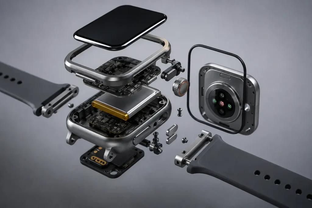
A functional enclosure defines the physical relationship among the display, PCB, battery, sensors, controls, antennas, charging interface, seals and strap connection. Prototype builds let product teams evaluate those relationships using progressively more production-representative materials and processes.
The goal is to discover packaging, machining, sealing and assembly risks while changes are still relatively inexpensive.
Why Wearable Enclosure Prototyping Is Difficult
A smartwatch enclosure prototype packs several mechanical and electronic interfaces into an unusually small volume.
The display occupies most of the front surface. A battery and PCB compete for depth inside the case. Optical sensors need controlled alignment to a rear window. Push buttons or a crown require travel and clearance around moving components. Antennas need suitable space around surrounding structures, while the back cover and bezel still have to remain stiff enough to preserve sealing geometry.
Typical enclosure features can include:
- Display seating and adhesive lands
- PCB locating bosses
- Battery-retention geometry
- Optical sensor apertures
- Microphone and speaker openings
- Side buttons or rotary crown interfaces
- Charging contacts
- Perimeter sealing features
- Strap lugs and pin holes
- Cosmetic exterior surfaces
Packaging volume can disappear quickly. A 2025 peer-reviewed study of a compact self-powered wearable vital-sign device reported an enclosure measuring 60 × 40 × 24 mm, while the complete wearable assembly reached 84 × 42 × 24 mm after its strap-related extension was included. The dimensions are reported in the published wearable IoT device study.
That example shows why enclosure size should be reviewed together with the components attached to it rather than as an isolated shell.
Choosing a Process for Wearable Enclosure Prototyping
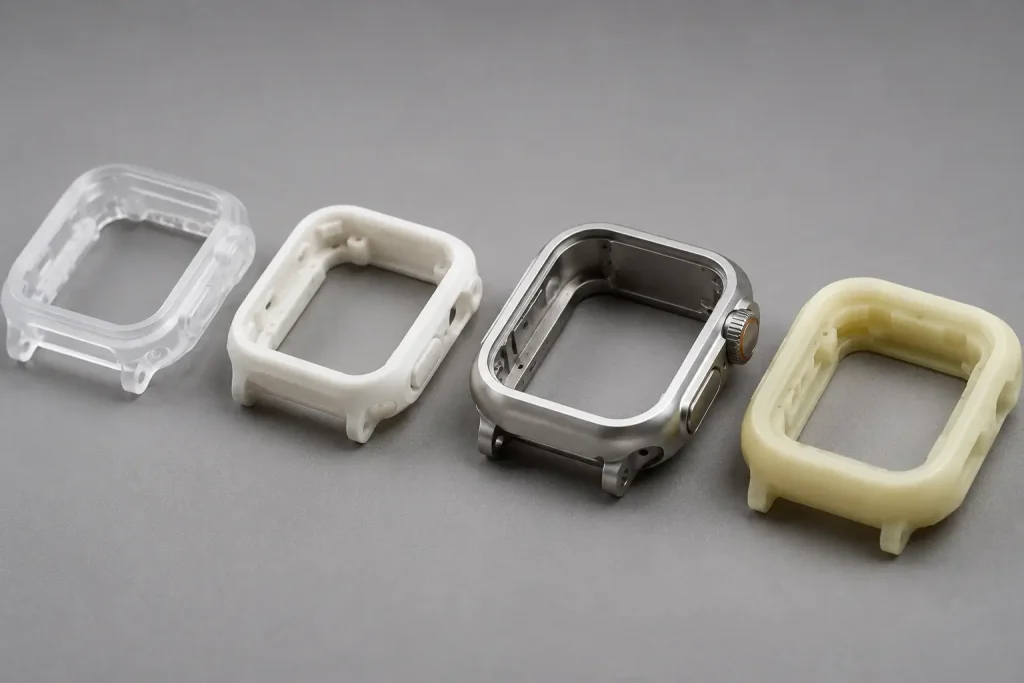
Different prototype stages answer different questions. Early wearable product prototyping may focus on wrist fit and visual proportions, while later builds need realistic wall stiffness, metal finishes, threads and sealing interfaces.
| Requirement | CNC Machining | SLA | SLS/MJF | Urethane Casting |
|---|---|---|---|---|
| Production-like metal housing | Excellent | Poor | Poor | Poor |
| Early wrist-fit evaluation | Good | Excellent | Excellent | Good |
| Precise openings and bosses | Excellent | Excellent | Good | Good |
| Functional threads | Excellent | Limited | Limited | Limited |
| Cosmetic evaluation | Excellent | Excellent | Moderate | Excellent |
| Rapid geometry changes | Good | Excellent | Excellent | Moderate |
| Small production-like batch | Good | Moderate | Good | Excellent |
SLA is useful for early appearance models, bezel proportions, button placement and internal packaging studies. Powder-bed polymer processes can suit durable concept housings where surface finish is secondary.
Once production-like metal behavior matters, prototype CNC machining can provide real threads, machined sealing lands, controlled display seats and functional mounting features without dedicated production tooling.
Urethane casting may become useful when several similar appearance prototypes are required before production tooling.
Process selection should therefore begin with the engineering question. A wrist-fit model does not need the same manufacturing route as an enclosure intended for functional assembly and sealing evaluation.
CNC Wearable Enclosure Prototyping: Thin Walls and Multi-Face Features
A CNC smartwatch housing often begins as a relatively thick billet and ends as a lightweight shell after most of the internal material has been removed.
That material-removal sequence changes part stiffness throughout machining. Thin walls can respond to cutting forces, residual stress and fixture pressure, particularly around wide display openings and deep internal cavities.
Common DFM concerns include:
- Narrow display bezels
- Thin side walls
- Deep internal pockets
- Small threaded bosses
- Button and crown openings
- Strap-lug holes
- Curved exterior surfaces
- Features distributed around several faces
Excessive clamping force can temporarily distort a thin housing. Once released from the fixture, the free-state geometry may shift. Unsupported walls can also vibrate during finishing and produce visible variation on cosmetic surfaces.
Practical designs leave usable clamping areas, avoid unnecessarily deep narrow pockets and use internal corner radii that real cutting tools can reach.
For cases with controls, lugs and curved surfaces distributed around the perimeter, 5-axis CNC machining can improve tool access and reduce repeated repositioning. The main advantage is access and setup reduction rather than automatically tighter tolerances.
💡 Pro Tip: Establish the datums that control the display, PCB, optical sensor and back cover before applying tight tolerances. Functional relationships usually deserve tighter control than a nearby cosmetic surface.
Displays, Sensors, Buttons and Charging Interfaces
The user-facing interfaces create some of the most demanding tolerance relationships in a wearable device enclosure.
A display opening needs more than the correct overall length and width. Engineers may also need to consider bezel uniformity, adhesive land width, glass seating height, edge gaps and the relationship between the display and surrounding controls.
Optical sensors create another stack. The sensor module on the PCB, enclosure aperture, transparent rear window and skin-facing surface must remain geometrically compatible after final assembly. Machining can control the physical position of these features, while optical and physiological performance remain complete-device validation responsibilities.
Buttons and crowns have their own mechanical chain. Shaft position, switch height, clearance, button travel, anti-rotation geometry and sealing features can occupy a very small area. A cutout that is dimensionally correct can still produce poor tactile behavior if another part in the assembly stack moves.
Charging interfaces introduce similar constraints. Pogo-pin contacts, conductive pads, magnetic features and wireless charging components have to fit around the back-cover architecture without disrupting sensor or gasket geometry.
For that reason, enclosure DFM is more effective when the supplier receives reference geometry for the PCB, display, battery and major interface components rather than only the exterior case model.
Sealing, Antennas and Thermal Design
Sweat, water and everyday handling place potential leak paths around almost every external interface.
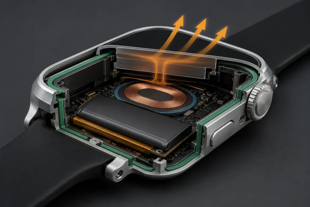
These paths can include:
- Display bonding surfaces
- Rear-cover joints
- Side buttons
- Rotary crowns
- Microphone openings
- Speaker membranes
- Sensor windows
- Charging contacts
Machining can create gasket grooves and flat sealing lands around a target ingress-protection architecture. The rating itself belongs to the tested complete product, including its adhesive, gasket, windows, controls and penetrations.
Metal housings introduce additional RF considerations. Antenna clearances, non-metal windows, grounding strategy and nearby internal structures should be reviewed during packaging development. The enclosure defines part of the physical RF environment, but antenna performance still requires testing of the assembled electronics.
Thermal behavior also differs from a stationary industrial controller because a wearable can remain in direct contact with the user.
Processor activity, wireless communication and battery charging generate heat inside a small enclosed volume. Aluminum can distribute that heat efficiently, which makes external surface temperature part of the system-level design problem.
A 2025 IEEE study of context recognition on wearable edge devices used a skin-temperature increase of no more than 1°C above ambient as its own thermal-comfort design criterion. The IEEE wearable edge-device study provides a useful example of how researchers explicitly include wearer comfort in thermal constraints.
That 1°C value is specific to the cited research framework and should not be reused as a universal smartwatch limit.
Strap Interfaces, Surface Finish and Skin Contact
The strap interface deserves structural attention because it transfers repeated user loads directly into the housing.
Integrated lugs, spring-bar holes, screw-mounted straps and quick-release structures require sufficient material around local load paths. Pin-hole alignment also affects whether a strap moves freely through its intended angle or rubs against the case.
An aluminum smartwatch enclosure can also use finishing to establish much of its final visual identity. Typical prototype finishes may include bead blasting, anodizing, polishing or combinations selected around the desired appearance and functional interfaces.
Drawings should distinguish between:
- Cosmetic exterior faces
- Hidden internal surfaces
- Display and bonding lands
- Grounding or electrical-contact areas
- Threaded features
- Closely fitted dimensions
- Areas requiring masking
Material selection needs similar care. An alloy designation by itself does not prove suitability for prolonged contact with skin. Exposure conditions, surface treatment and the finished product requirements all matter.
For medical wearable devices, the current ISO 10993-1:2025 biological evaluation standard provides requirements and general principles for evaluating biological safety within a risk-management process. The 2025 document is the sixth edition and replaces the withdrawn 2018 edition.
A machining supplier can manufacture the specified geometry, material and finish. Biological evaluation remains part of the finished medical-device program.
Real-World Example: A Wearable for Assisted Living
[IMAGE SUGGESTION: Research-grade BLE smart wristband beside indoor positioning beacons in an assisted-living environment, with electronics and test equipment visible, no text.]
Wearable packaging decisions also influence power and wireless-system behavior.
A 2025 Sensors study developed a custom Bluetooth Low Energy wristband and configurable beacon system for indoor positioning in ambient assisted-living applications. Researchers chose custom hardware because they needed control over sensing, communication and power-management behavior.
The published BLE device study reported approximately 2–3 weeks of wristband autonomy and 3–4 months for the beacons under the tested configurations.
The important enclosure lesson comes from the system relationship behind those numbers.
Battery capacity needs physical volume. Sensors need defined orientation and location. Antennas need a usable RF environment. A body-worn device also needs an enclosure that supports attachment and everyday handling without consuming excessive space.
This creates a different engineering problem from a generic example where a prototype simply breaks and a stronger material replaces it. Here, the development challenge is balancing packaging volume, energy autonomy, sensing and communication in the same wearable platform.
The published project is a research example rather than a BOONA customer case, and its battery results should not be treated as specifications for other wearable products.
From Form Model to Functional Wearable Prototype
A staged prototype program prevents a single expensive build from carrying every design question.
Stage 1: Form and Ergonomic Model
Early models can evaluate:
- Wrist fit
- Overall thickness
- Display proportions
- Strap angle
- Button location
- Exterior shape
At this stage, fast geometry changes may matter more than production-like material.
Stage 2: Engineering Packaging Prototype
The next build should include representative PCB, battery, display, sensors and controls. Assembly sequence, internal clearance and tolerance stack become more important.
Stage 3: Functional Enclosure
Production-representative materials can then test wall stiffness, threads, sealing surfaces and finish behavior. For aluminum designs, aluminum CNC machining allows the prototype to incorporate real internal pockets, interfaces and machined exterior features.
Stage 4: Pre-Production Validation
Later prototypes should represent the intended material, surface finish, tolerance relationships and assembly architecture closely enough for complete-device validation.
A useful RFQ at this stage includes the enclosure STEP file, controlled 2D drawing, PCB model, display geometry, battery envelope, sensor positions, strap interfaces, surface-finish requirements and critical dimensions.
Providing those references allows DFM review to concentrate on the features that control actual product function.
Common Smartwatch Prototype Mistakes
Several recurring decisions increase enclosure risk.
Making Every Wall as Thin as Possible
Reducing mass can be useful, but local stiffness around the display, controls, strap connection and fasteners may be more important than minimizing every wall.
Designing the Exterior Before the Internal Stack
A compact case can become difficult to assemble once real battery thickness, PCB components and connector clearances replace simplified CAD envelopes.
Ignoring Tool Access
Deep square corners, narrow cavities and hidden undercuts can require smaller tools, additional setups or geometry changes.
Adding Sealing Features Late
A gasket needs space, compression control and suitable screw spacing. Adding it after the enclosure architecture is nearly finished can interfere with the PCB or reduce wall support.
Leaving Functional Datums Undefined
Display fit, optical alignment and button behavior depend on relationships between components. Tight tolerances on unrelated cosmetic surfaces do little to control those interfaces.
Selecting Anodizing Only by Appearance
Coating decisions can affect dimensions, electrical contact areas and masking requirements.
Calling the Machined Housing IP-Rated
The enclosure can contain geometry intended for a target IP configuration. Only the validated complete assembly establishes the final rating.
FAQs
What is the best way to prototype a smartwatch enclosure?
Early additive-manufactured models are useful for evaluating form, wrist fit and packaging. CNC machining becomes more valuable when the project needs production-like metal, functional threads, accurate interfaces and realistic surface finishing.
Can a smartwatch enclosure be CNC machined from aluminum?
Yes. CNC machining can produce internal cavities, display openings, PCB bosses, button interfaces, sensor apertures, strap features and sealing geometry in aluminum.
Should I use CNC machining or 3D printing for a wearable prototype?
Use 3D printing when rapid geometry iteration and ergonomic evaluation are the main objectives. CNC machining is better suited to later prototypes that need fully dense metal, machined interfaces and production-representative wall behavior.
Can CNC machining produce a waterproof smartwatch enclosure?
CNC machining can create controlled gasket grooves, sealing lands and accurate cover interfaces. The finished wearable still needs appropriate complete-device validation before an ingress-protection rating is claimed.
What information should I send for a wearable enclosure quote?
Provide the 3D CAD model, controlled drawing, material, finish, quantity and critical dimensions. Reference geometry for the PCB, display, battery, sensors, controls and strap interface can improve the DFM review.
Is aluminum suitable for skin-contact wearable products?
Aluminum can be used in wearable housings, but suitability depends on alloy, finish, exposure conditions and product requirements. Medical wearables may require biological evaluation within the applicable regulatory and standards framework.
Conclusion: Prototype the Enclosure as Part of the Wearable System
Effective wearable enclosure prototyping treats the housing as part of the complete product architecture.
Display position, PCB datums, sensor alignment, battery volume, controls, antennas, sealing surfaces, strap loads, thermal behavior and cosmetic finish all compete for space within a compact housing. A change to one interface can alter several others.
The most useful development route therefore progresses from the question the prototype needs to answer. Early printed models can validate proportion and wrist fit. Engineering builds can resolve packaging and assembly. Later CNC prototypes can evaluate production-like metal geometry, functional interfaces and surface finishing before the design is frozen.
For a smartwatch, fitness tracker, medical wearable or other body-worn electronics project, prepare the enclosure CAD together with assembly references and critical interface requirements. BOONA can review the design through its prototype CNC machining service before material is cut. No MOQ. Send your CAD for a free DFM review.


