A robot arm can lose repeatability long before the controller shows an error.
The servo is fine. The encoder reads correctly. The program has not changed. But the tool center point starts drifting. A joint feels slightly loose. A link flexes under payload. A motor bracket shifts after repeated motion. The arm still moves, but it no longer moves the same way every cycle.
That is why robot arm components need serious machining control.
Joints, links, brackets, actuator housings, bearing seats, motor mounts, and tool interface plates all shape how a robot arm behaves under load. Software can tune motion, but it cannot fully fix poor bearing alignment, weak link stiffness, or a bracket that flexes during acceleration.
For robotics engineers, automation integrators, OEM buyers, and sourcing teams, CNC machining offers a practical way to build custom robot arm parts from real engineering materials before tooling or mass production makes sense.
Why Robot Arm Components Need Precision Machining
Robot arm components are motion-control hardware, not just metal shapes cut from a CAD model.
A robot arm depends on mechanical alignment at every axis. If a bearing bore is loose, the joint can develop play. If a reducer seat is not flat, torque transfer becomes uneven. If a link is too flexible, the payload may stay within the robot’s rated load but still affect accuracy. If a sensor bracket vibrates, calibration may become unreliable.
The demand for robot arm hardware is not slowing down. The International Federation of Robotics reported 4,281,585 industrial robots operating in factories worldwide in 2023, a 10% increase, and 541,302 new industrial robot installations in the same year. That scale matters because more robots in production means more machined parts must hold alignment, survive cycles, and support repeatable assembly.
A useful reference point is ISO 9283, which covers performance criteria and test methods for manipulating industrial robots, including accuracy and repeatability. That standard is about robot performance, not machining directly, but it reinforces the same point: repeatable robot behavior depends on measurable mechanical and motion characteristics.
For teams moving from CAD to functional hardware, Boona custom CNC machining service supports metal and plastic robot arm parts for prototypes, validation builds, and low-volume production.
Key Robot Arm Components Made by CNC Machining
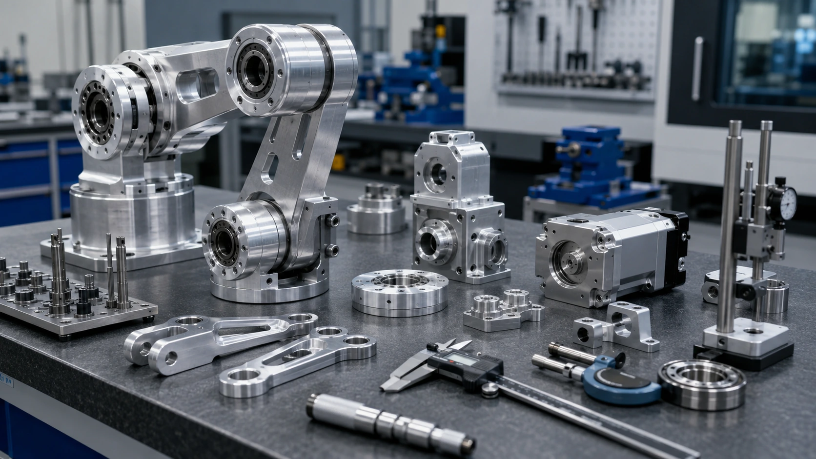
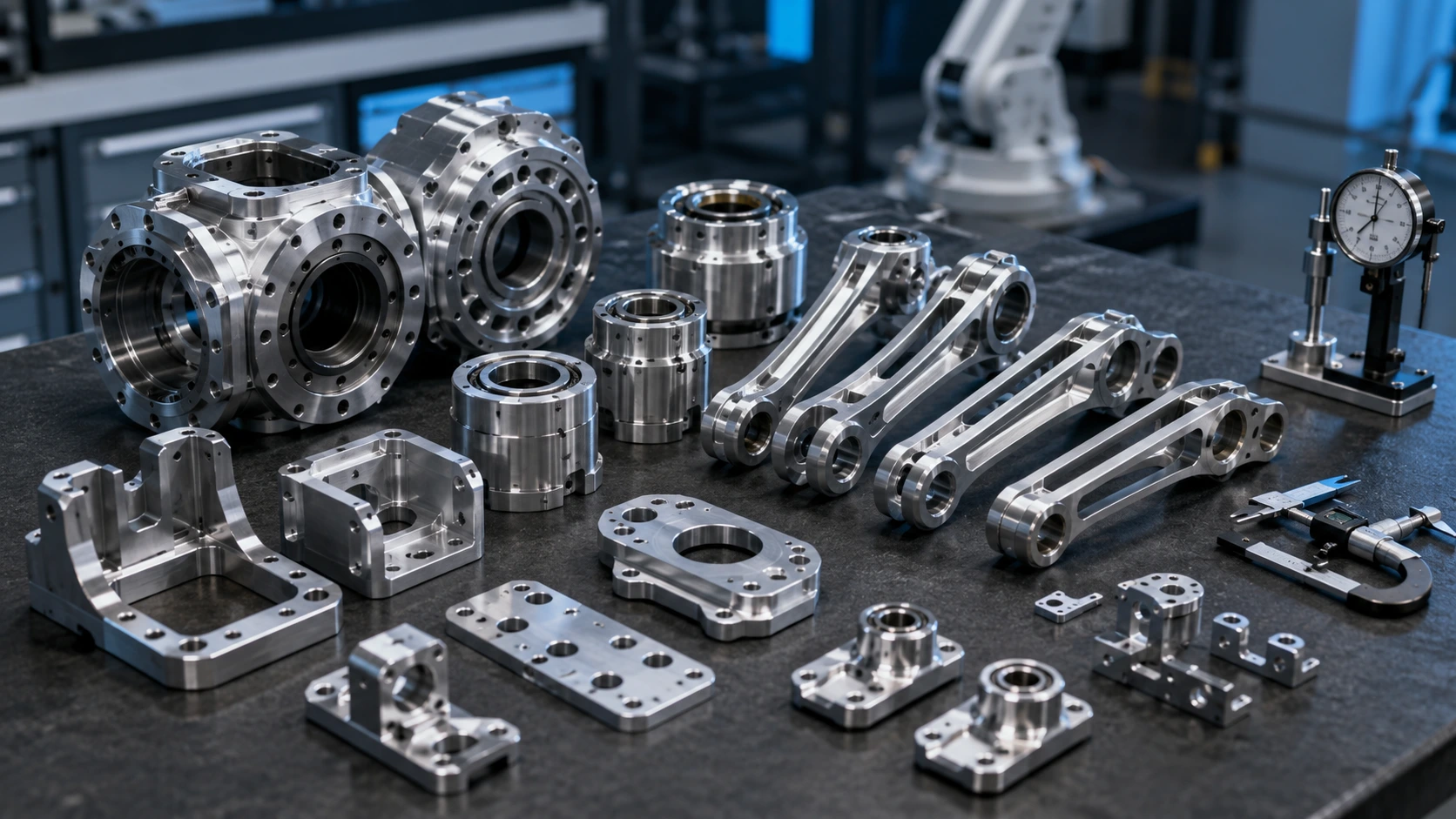
CNC machined robot arm parts usually fall into three core groups: joints, links, and brackets. Each group has a different job.
Joints control rotation and load transfer. Shoulder joints, elbow joints, wrist housings, bearing carriers, reducer mounting rings, joint side plates, shaft support blocks, and dowel-located interfaces all affect motion smoothness. These parts often need tighter control because small errors can create backlash, vibration, noise, or uneven bearing wear.
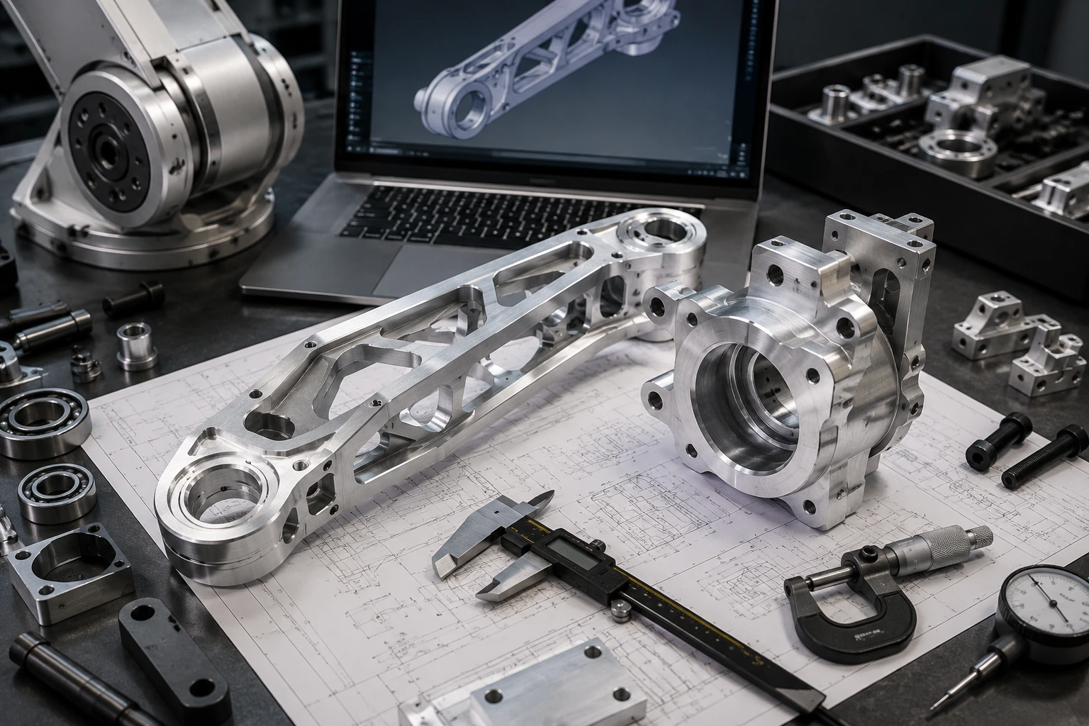
Links transfer force between joints. Upper arm links, forearm links, pocketed aluminum links, ribbed structures, hollow link bodies, and connecting plates must stay light without giving up stiffness. A link that looks efficient in CAD may still deflect under acceleration, especially when the tool or payload sits far from the joint.
Brackets look simpler, but they often control important secondary systems. Motor brackets, encoder brackets, camera mounts, cable routing brackets, tool interface brackets, and cover supports affect alignment, wiring safety, assembly access, and serviceability.
| Robot Arm Component | Why CNC Machining Is Used | Common Material |
|---|---|---|
| Joint housing | Bearing and reducer alignment | Aluminum 6061 / 7075 |
| Arm link | Lightweight stiffness | Aluminum 6061 / 7075 |
| Bearing carrier | Smooth rotation and load support | Aluminum / steel |
| Motor bracket | Accurate motor positioning | Aluminum / steel |
| Sensor bracket | Stable calibration position | Aluminum / stainless steel |
| Tool interface plate | Repeatable EOAT mounting | Aluminum 6061 / 7075 |
For a wider view of robotics hardware, the related guide on CNC machining for robotics covers actuator housings, frames, sensors, grippers, and other robot platforms.
Machining Robot Arm Joints and Bearing Interfaces
Robot arm joint machining has a direct effect on motion smoothness, repeatability, backlash, and service life.
A joint housing may control the bearing fit, reducer location, shaft alignment, motor interface, bolt pattern, and mating face flatness at the same time. If one of these features is wrong, the part may still assemble, but the arm may not run cleanly after cycling.
Common joint features include bearing bores, reducer seats, reamed dowel holes, bolt circles, shaft holes, mating faces, grease channels, and cable passages. Bearing bores may need H7-style fits depending on the bearing and assembly method. Reducer faces may need flatness control. Dowel holes may need true position control so the joint can be disassembled and reassembled without losing alignment.
The goal is not to make every dimension extreme. The goal is to control the features that affect motion.
For robot arm bearing seats, the machining process may include roughing, stress relief where needed, finish boring, reaming, or final inspection with bore gauges and CMM. Multi-sided joint housings also need careful fixture planning. If the setup is not controlled, one face may be accurate by itself but wrong relative to the next face.
Boona precision machining capability is useful when bearing bores, dowel holes, reducer interfaces, or mating faces decide whether the robot arm moves correctly.
Machining Robot Arm Links Without Losing Stiffness
Robot arm links are where many teams fight the same problem: weight versus stiffness.
A lighter link helps acceleration, braking, payload response, and motor sizing. But a weak link hurts repeatability. A robot arm link does not need to break to cause trouble. It only needs to flex enough to move the tool center point under load.
CNC machining gives engineers several options: pocketed aluminum structures, ribbed geometry, hollow link bodies, thin-wall sections, and high-strength aluminum alloys. Aluminum 6061 works well for general-purpose links and prototype structures. Aluminum 7075 can make sense for compact, high-load, or weight-sensitive links where stiffness and strength justify the cost.
The design trade-offs matter. Deep pockets increase cycle time. Thin walls may chatter during cutting or deform during clamping. Small internal radii require small cutters. Aggressive hollowing can weaken load paths around bearing zones, bolt bosses, dowel holes, and joint interfaces.
A better strategy is to protect stiffness first, then remove weight from low-stress areas. Keep material around joint faces, bearing supports, and fastener zones. Use cutter-friendly internal radii. Avoid making the part look lightweight at the cost of assembly stability.
My view is simple: optimize stiffness before chasing the last few grams. A lighter link that flexes too much is not an upgrade.
Robot Arm Brackets: Simple Parts With Real Alignment Risk
Brackets are easy to underestimate because they often look like small plates with holes.
In a robot arm, that assumption can be expensive.
A motor bracket does not just hold a motor; it helps control shaft alignment and vibration. An encoder bracket may look minor until a small offset affects feedback quality. A sensor bracket can change calibration if it flexes during arm motion. A cable routing bracket can damage wiring if its edges are not broken properly. A tool interface bracket may affect end-effector position if the mounting pattern is not controlled.
This is why robot arm brackets should be reviewed by function. A cover bracket can usually use general tolerances. A camera bracket, motor bracket, or tool interface plate may need flatness, hole position, dowel features, or controlled perpendicularity.
Material choice follows the same logic. Aluminum is often enough for lightweight brackets. Stainless steel may fit wear-prone or high-load areas. POM or nylon may work for cable guides and low-friction supports. The finish also matters: black anodizing near optical systems, smooth edge breaks near cables, and passivation for stainless parts in corrosive environments.
Good brackets are not overcomplicated. They are easy to machine, easy to assemble, hard to misalign, and safe for nearby cables and sensors.
Materials, Tolerances, and Finishing for Robot Arm Parts
Precision robot arm components should be material-selected by function, not habit.
Aluminum 6061 is often the practical starting point for brackets, housings, plates, covers, and prototype links. It machines well, keeps weight low, accepts anodizing, and offers a good balance between cost and performance. Aluminum 7075 is better for high-strength, lightweight structures such as arm links, joint plates, and compact load-bearing brackets.
Stainless steel fits shafts, pins, inserts, wear areas, and high-load brackets. It is heavier than aluminum, but it handles contact and corrosion well. POM/Delrin works for cable guides, low-friction supports, and wear blocks. PEEK may be used for heat resistance, insulation, wear resistance, or chemical stability. Copper and brass usually appear in heat spreaders, grounding features, bushings, fittings, or conductive parts.
Tolerance planning should stay function-first. Bearing bores, reducer seats, motor mounting faces, dowel pin holes, shaft holes, joint mating surfaces, tool interface patterns, and sensor alignment features deserve closer control. Non-critical profiles, clearance slots, lightening pockets, and cosmetic surfaces can often use general tolerances.
Finishing also has a functional role. Anodizing protects aluminum. Black anodizing can reduce reflection near cameras. Hard anodizing may improve wear resistance, but it can change dimensions on bores and sliding fits. Deburring matters near harnesses, cable slots, thread starts, sensor brackets, and hand-access areas.
A strong drawing separates functional datums from cosmetic geometry. That saves cost without weakening the robot arm.
Prototype, Low-Volume Builds, and Process Choice
Robot arm development rarely moves in a straight line.
A motor size changes. A reducer supplier changes. A link length changes after workspace testing. Cable routing needs more clearance. A sensor moves. Payload requirements increase. The end-effector changes, and suddenly the wrist plate needs a new interface.
CNC machining fits this development pattern because it does not require mold tooling. A team can machine five parts, test them, revise the CAD model, and machine twenty more. That flexibility is useful for industrial robot arms, collaborative robots, inspection arms, lab automation systems, and custom manipulators.
3D printing still has a place. Printed parts work well for early shape checks, cover layouts, cable routing mockups, and non-load prototypes. The problem starts when printed parts are asked to behave like machined joint housings, load-bearing links, or motor mounts. Printed parts can check form. Machined parts test function.
For related process context, the article on CNC machining for robot grippers and end effectors shows how CNC machining and 3D printing can work together for functional robot tooling.
For low-volume robot arm parts, quantities may stay small for months: 5 pieces for a prototype, 10–20 for validation, 50 for pilot production, and repeat batches for customer testing. At those volumes, CNC machining often gives the best balance of speed, material performance, and revision flexibility.
Cost Drivers, DFM, and Inspection Planning
Robot arm parts become expensive when lightweight structure, tight interfaces, difficult materials, and low quantities all appear in the same design.
Material is one driver. 7075 aluminum and titanium cost more than 6061. Stainless steel machines slower than aluminum. PEEK costs more than common plastics. Geometry adds more cost: deep pockets, thin walls, small internal radii, long-reach tools, and multi-sided features increase machining time.
Tolerance adds another layer. Tight tolerance everywhere increases inspection time and setup risk. Finishing can also raise cost when hard anodizing, masking, polishing, plating, or surface roughness requirements affect critical features.
| Cost Driver | Why It Raises Cost | Better Practice |
|---|---|---|
| Deep pockets | Longer machining time | Add radii and improve access |
| Thin walls | Chatter and workholding risk | Keep practical wall thickness |
| 7075 / titanium | Higher material and tool cost | Use only where function requires |
| Tight tolerance everywhere | More machining and inspection | Control functional features only |
| Hard anodizing | Finish buildup can affect fits | Protect critical bores |
| Low volume | Setup cost spreads over fewer parts | Batch similar parts |
Inspection should match risk. A cover bracket does not need the same report as a joint housing. Critical checks may include bearing bores, reducer seats, motor mounting holes, dowel holes, tool interface plates, sensor faces, threaded holes, and visible burrs. Calipers, micrometers, bore gauges, pin gauges, thread gauges, height gauges, CMM inspection, and surface roughness checks may all be used depending on the part.
💡 Pro Tip: For robot arm links and brackets, do not remove material equally everywhere. Keep stiffness around joint interfaces, bearing zones, dowel holes, threaded features, and load paths. Remove weight from low-stress areas instead.
RFQ Checklist for Robot Arm Components
A STEP file shows geometry. It does not explain how the robot arm uses the part.
For accurate quoting, buyers should send a 3D CAD file, a 2D drawing, material requirement, quantity, prototype or production stage, application location on the robot arm, payload or load condition, bearing or reducer details, motor interface requirements, cable routing needs, critical tolerances, GD&T if required, finish, inspection report needs, lead time, and packaging requirements.
A short function note helps even more:
“Aluminum 7075 robot arm link, 20 pcs, black anodized, lightweight pocketed design, bearing interface tolerance required, CMM report for critical features.”
Now the supplier understands the part’s role. It is not just a long aluminum link. It is a load-transfer component with stiffness, weight, and joint interface requirements.
If the part is structural, say so. If it only supports a cover, mention that too. If sensor alignment matters, explain the calibration risk. Better input usually leads to better DFM feedback, better pricing, and fewer revisions.
Related Reading
For broader robot hardware planning, read our guide to CNC machining for robotics. If your team works on humanoid platforms with compact actuators and joint structures, the article on humanoid robot parts machining provides useful context. For EOAT and tooling interfaces, review our guide to CNC machining for robot grippers and end effectors.
Conclusion: Robot Arm Components Need Function-First Machining
Robot arm components are the mechanical foundation behind repeatability, payload stability, tool center point accuracy, and long-term arm performance.
Successful machining starts before cutting begins. Choose materials based on load, weight, wear, heat, and cost. Put tight tolerance only on functional interfaces. Protect bearing bores, reducer seats, motor faces, dowel holes, and joint mating surfaces. Reduce link weight carefully without weakening load paths. Use finishing and deburring to protect cables, sliding areas, optical systems, and assembly safety. Inspect the features that affect motion.
For robot arm prototypes, validation builds, and low-volume production, CNC machining gives engineers real materials, accurate interfaces, and room to revise designs before tooling makes sense.
If you are developing robot arm joints, links, brackets, actuator housings, bearing carriers, or tool interface plates, send your CAD files, drawings, and application notes to Boona custom CNC machining team. We can help review material, tolerance, DFM, finishing, and inspection requirements before machining starts.
FAQs
What are the main components of a robot arm?
The main robot arm components include joints, links, brackets, actuator housings, motor mounts, bearing seats, tool interface plates, sensor mounts, and cable routing parts. These parts control motion, stiffness, payload, tool positioning, assembly repeatability, and long-term robot arm performance.
Why are robot arm components CNC machined?
Robot arm components are CNC machined because many parts need accurate bearing fits, motor alignment, threaded holes, stiff structures, lightweight geometry, and repeatable assembly. CNC machining also allows prototype and low-volume robot arm parts to be tested in real engineering materials.
What materials are best for robot arm components?
Aluminum 6061 is common for general robot arm brackets, housings, and prototype links. Aluminum 7075 is better for high-strength lightweight links and joint plates. Stainless steel suits shafts, pins, and wear parts, while POM, PEEK, nylon, copper, and brass serve specific friction, thermal, or electrical needs.
What tolerances matter for robot arm joints?
Critical tolerances for robot arm joints usually include bearing bores, reducer seats, motor mounting faces, dowel holes, shaft holes, and joint mating surfaces. Non-critical pockets, cover features, and clearance slots can often use general tolerances to reduce cost.
Is CNC machining better than 3D printing for robot arm parts?
CNC machining is better for functional robot arm joints, links, brackets, bearing seats, motor mounts, and load-bearing hardware. 3D printing is useful for early shape checks, cable routing mockups, non-load covers, and concept models before the design moves into real material testing.
How can buyers reduce robot arm machining cost?
Buyers can reduce robot arm machining cost by simplifying deep pockets, avoiding unnecessary tight tolerances, using standard materials and threads, batching similar parts, defining finishes clearly, and sending complete drawings. Good DFM should reduce cost from non-functional areas without weakening the arm.