
A tooling drawing reaches the mold supplier with MT-11030 specified across the main housing, MT-11555 around a grip area, and polished surfaces surrounding a display opening. The CAD model looks straightforward until DFM begins. Where exactly should each texture stop? Does the wall have enough draft? Can the texture cross a parting line? Will the selected resin reproduce the intended appearance?
These are the practical questions behind mold texture codes.
An MT callout affects more than appearance. Texture interacts with draft, ejection, tooling geometry, resin behavior, surface inspection and the location of parting lines or inserts.
Engineers should also avoid treating MT-11010 through MT-11555 as one simple roughness ladder. Mold-Tech texture codes identify individual patterns. The complete specification still depends on the approved texture reference, feature geometry, resin, molding conditions and part design.
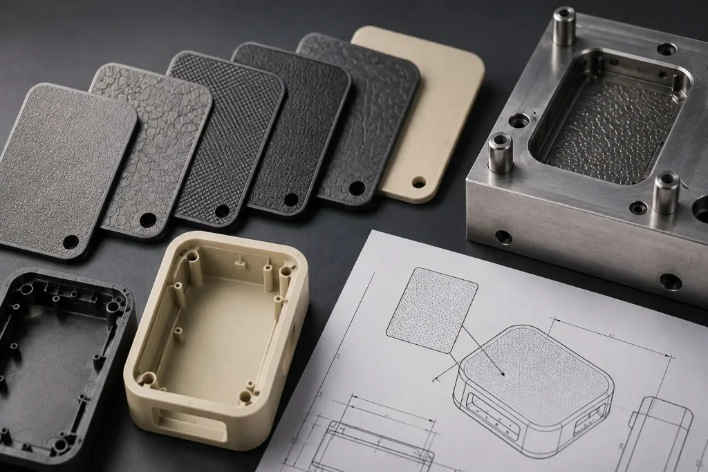
What Do Mold Texture Codes Tell the Moldmaker?
A texture code provides the tooling team with a reference for the surface pattern expected on the molded part.
The number alone does not define every manufacturing condition. A useful specification should also identify:
- Exact MT designation
- Surfaces receiving the texture
- Texture boundaries
- Pattern orientation where relevant
- Areas remaining polished or untextured
- Parting-line treatment
- Logo and lettering zones
- Production resin and color
- Approved physical texture reference where appearance is critical
The MT-11010 texture, for example, should be interpreted as a specific texture designation rather than automatically translated into a single Ra value.
Designed textures contain spatial information. Feature size, spacing, direction, peak geometry and valley geometry all influence how the molded surface looks and feels.
Two surfaces can therefore produce similar average roughness values while reflecting light differently.
Texture should enter DFM before final tooling geometry is frozen. BOONA injection mold tooling service is the appropriate stage to review draft, pull direction, slides, shutoffs and cosmetic surfaces together.
Reading MT-11010 Through MT-11555
The safest way to interpret the MT range is as a catalog of individual texture references rather than a continuously increasing numerical scale.
When a drawing specifies MT-11010, MT-11120 or MT-11555, the first question should be: which approved texture reference controls the final appearance?
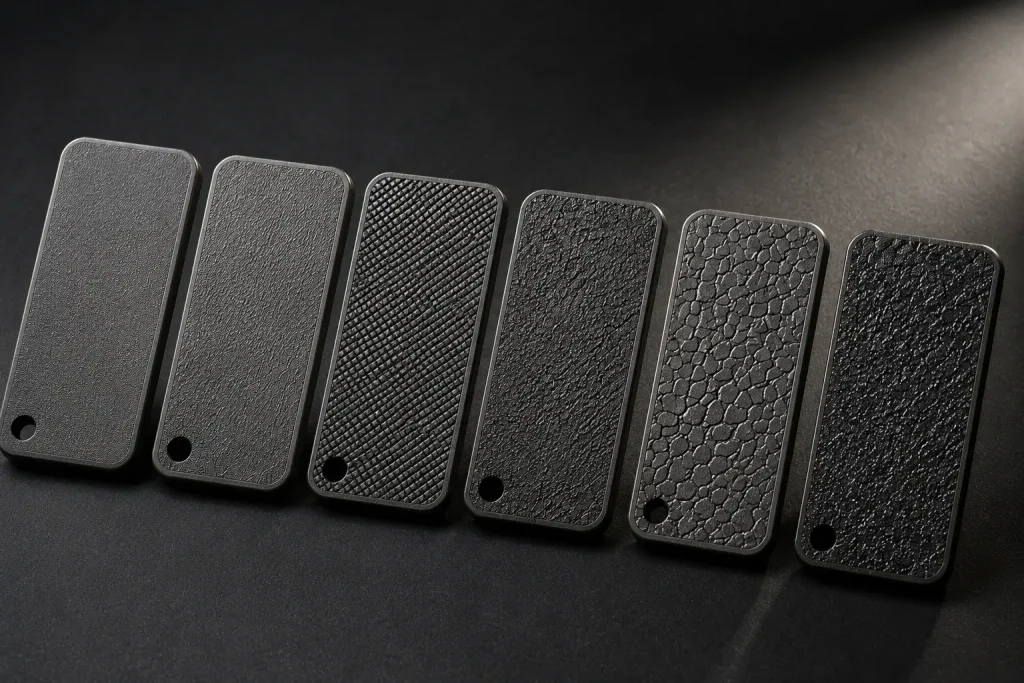
| MT Callout | Practical Interpretation | Confirm Before Tooling |
|---|---|---|
| MT-11010 | Specific fine MT texture | Plaque, depth, draft |
| MT-11020 | Separate MT pattern | Appearance, resin, draft |
| MT-11030 | Individual texture selection | Boundary, depth, release |
| MT-11120 | Separate code-group pattern | Plaque, orientation, location |
| MT-11550 | More pronounced pattern requiring direct review | Depth, draft, parting lines |
| MT-11555 | Specific MT pattern | Approved sample, depth, draft |
This table deliberately avoids publishing universal texture depths or required draft angles.
Those figures should come from the controlling texture specification or approved Mold-Tech reference used for the actual mold.
A larger code number alone does not tell an engineer enough to predict gloss, tactile feel, depth or ejection behavior.
The MT-11555 texture therefore deserves the same direct sample review as any other appearance-critical texture, particularly where it covers a large visible surface.
Texture Depth Is Different From Surface Roughness
An injection mold texture can be described at several scales.
Texture depth usually refers to larger designed peaks and valleys that create the intended visual or tactile pattern. Surface-metrology parameters quantify selected aspects of smaller-scale topography.
Common profile parameters include Ra and Rz. Areal measurement adds parameters such as Sa, Sq and Sz.
The current ISO 25178-2:2021 defines terms and parameters for areal surface-texture evaluation.
This distinction explains why an MT code should not be replaced casually with one Ra number.
Ra describes the arithmetic mean deviation of a profile. Sa applies a similar averaging concept across an area. Neither one alone communicates the entire pattern geometry.
A fine irregular grain and a more uniform technical texture could produce overlapping amplitude measurements while remaining visibly different.
BOONA guide to SPI, VDI 3400 and Ra addresses the same issue from the mold-polishing and EDM-finish side.
For appearance-critical parts, use the MT code to control pattern identity and use quantitative metrology only where the drawing genuinely needs measurable acceptance criteria.
Why Mold Texture Codes Must Be Reviewed With Draft
Texture changes the ejection condition.
As a molded part cools, the polymer shrinks around core geometry and against textured mold surfaces. During ejection, the molded texture must release from corresponding steel features without excessive rubbing.
Insufficient draft can contribute to:
- Drag marks
- Polished streaks
- Texture damage
- Difficult ejection
- Local whitening
- Part distortion
- Higher ejector loads
A 2025 peer-reviewed study of draft angle and texture replication evaluated eight draft angles between 0° and 3.5°.
The researchers found that draft angle significantly affected surface-texture replication, while its influence on the overall dimensional-deformation trend was more limited.
That result is useful because it shows that draft affects more than whether a component physically leaves the mold.
A mold texture draft angle should therefore be reviewed together with texture geometry, wall height, resin, pull direction and the ejection system.
💡 Pro Tip: Approve the intended texture before finalizing marginal draft surfaces. A late change to a stronger texture can turn a previously acceptable wall into an ejection-risk area.
Why One Draft Rule Cannot Cover Every MT Texture
General rules such as adding a fixed number of draft degrees for a given texture depth can help during concept screening. They should not become universal drawing requirements.
A short cosmetic rim behaves differently from a tall housing wall even if both carry the same MT callout.
Material also matters. PP, ABS, PC and filled engineering plastics have different shrinkage and surface-replication behavior.
Review variables such as:
- Texture pattern and depth
- Wall height
- Resin family and grade
- Mold shrinkage
- Pull direction
- Core or cavity location
- Part stiffness
- Ejection method
- Nearby ribs and bosses
- Slides and lifters
The reference edge used for draft also matters.
Adding draft from the wrong edge may improve release while moving a mating feature or changing the visible product outline.
A drawing should therefore communicate which geometry controls the final dimension instead of adding texture as a cosmetic note after the CAD model is complete.
Draft analysis and texture specification work best as one DFM task.
Resin and Molding Conditions Change Texture Replication
The mold surface creates the pattern, but the polymer and process determine how faithfully the finished component reproduces it.
A 2023 peer-reviewed study of textured automotive ABS and PP components found that processing conditions had a substantial effect on measured surface topography.
Across the reported tests, changes in tooling temperature and injection speed produced variations of approximately:
- 40% in Sa and Sdq
- 35% in Vmc
- 50% in Sk
The researchers also found that ABS and PP did not respond identically to the investigated processing variables.
That matters during cosmetic approval.
The same tool texture may appear different across:
- ABS
- PP
- PC
- PC-ABS
- PA
- Glass-filled polymers
- Mineral-filled materials
Pigment, filler content, melt temperature, tool temperature, injection speed and holding conditions can all affect replication and gloss.
A physical plaque molded in a different resin may therefore be useful for selecting the general pattern while remaining an imperfect predictor of production appearance.
For a production-intent project, texture approval should ideally use the intended resin and color. BOONA plastic injection molding service is where tool texture and actual material processing finally interact.
Published Example: Automotive Interior Texture Replication
The same 2023 automotive study provides a useful real-world example because the failure mode involved cosmetic replication rather than broken components.
Researchers used a rectangular mold cavity measuring approximately 138 × 78 mm with a 2.7 mm cavity thickness.
The tooling incorporated three EDM-generated texture regions. The study compared ABS with a PP grade containing 15% talc by weight.
The issue was subtle: two molded surfaces could appear similar at first glance while showing measurable differences in topography and light reflection.
Changing mold temperature and injection speed altered multiple texture parameters. Under the tested conditions, the researchers found that ABS surface topography was less sensitive than PP to some of those process changes.
For automotive interior trim, control panels or console parts, these differences can matter because adjacent components are often viewed under directional daylight or cabin illumination.
The same principle applies to consumer housings and industrial controls.
A texture code establishes the target pattern, while resin and process stability influence how consistently production parts reproduce it.
This is a published research example rather than a BOONA customer case.
Parting Lines, Shutoffs and Texture Boundaries
Texture becomes more difficult to control around mold construction features.
Review the texture strategy around:
- Parting lines
- Slides
- Lifters
- Inserts
- Shutoffs
- Venting areas
- Ribs
- Bosses
- Display openings
- Sealing surfaces
- Snap-fit features
A texture crossing two separate mold components can reveal slight differences in alignment or pattern transition.
Texture stopping near a shutoff also needs a deliberate boundary. Leaving the decision to the toolmaker can produce a result that is manufacturable but visually different from the industrial-design intent.
Sealing surfaces need particular care. Cosmetic grain should not extend automatically onto a land that requires controlled contact.
Logos and lettering create another transition problem. Fine embossed or debossed characters can lose definition when a strong grain approaches their edges.
A drawing should therefore specify whether lettering:
- Shares the surrounding texture
- Remains polished
- Uses a texture-free border
- Receives a separate finish
Tool steel can also influence the wider finishing strategy. BOONA P20 vs H13 vs NAK80 vs S136 mold steel guide covers how polishing, corrosion, wear and molding requirements affect steel selection.
Why Physical Texture Plaques Matter
Computer rendering helps teams compare broad texture directions, but a screen is a poor final cosmetic standard.
Lighting angle changes shadow depth. Exposure alters contrast. Image compression removes fine details. Different monitors display the same photograph differently.
A physical texture plaque becomes particularly useful when:
- Appearance is brand-critical
- Two similar MT textures are under review
- Adjacent parts use different resins
- Texture covers a large visible area
- Color strongly changes perceived gloss
- Pattern orientation matters
- Customer and moldmaker need one approval reference
A practical development sequence is:
CAD rendering → texture reference → molded plaque → production-intent sample
The plaque itself should also be documented.
Record the MT code, resin where relevant, color, approval status and any specific viewing conditions.
The customer and mold supplier should agree which reference controls if a photograph, drawing note and physical plaque appear inconsistent.
A signed sample removes much of the ambiguity that otherwise appears during final cosmetic approval.
Mold Texture Codes vs SPI, VDI 3400 and Ra
MT, SPI, VDI and roughness measurements all describe surface condition, but they serve different purposes.
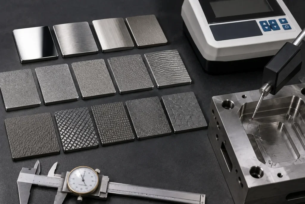
| System | Primarily Describes | Typical Use |
| Mold-Tech MT | Specific patterned texture | Decorative and tactile molded surfaces |
| SPI | Mold polishing / preparation class | Gloss through matte surfaces |
| VDI 3400 | EDM-related texture grade | Controlled technical matte textures |
| Ra / Sa | Quantitative surface parameters | Surface metrology |
Problems appear when engineers try to create exact one-to-one conversions between them.
An MT grain contains spatial pattern information that a single Ra value cannot represent.
SPI classes relate strongly to mold preparation and polishing. VDI grades represent another texture framework. Ra and Sa provide measured quantitative information.
Measured roughness can still be extremely useful, especially where a functional surface requires inspection.
The safer approach is to identify one controlling specification and then add other parameters only where they serve a clear function.
For example, an appearance surface might use an MT texture code plus an approved physical plaque, while a nearby sealing land receives a measured surface-texture requirement.
Common Mold Texture Code Specification Mistakes
Several recurring mistakes create unnecessary questions during tooling.
Assuming Higher MT Numbers Always Mean Rougher
Treat each MT designation as an individual texture reference. Do not infer depth solely from the number.
Writing Only “Mold-Tech Finish”
Specify the exact code and the surfaces that receive it.
Adding Texture After Draft Is Finalized
Draft and texture interact during ejection. Review them together.
Replacing MT With Ra
Average roughness cannot completely define a designed pattern.
Leaving Texture Boundaries Undefined
Show where grain stops around parting lines, logos, sealing lands and adjoining finishes.
Approving Texture From a Photograph Alone
Photographs help communication. Physical plaques give teams a stronger cosmetic reference.
Ignoring Production Resin
Material and processing conditions influence texture replication and gloss.
Applying One Draft Angle Everywhere
Wall height, resin, pull direction and texture geometry can create very different release conditions.
Resolving these questions during DFM is generally easier than modifying finished mold steel after texture application.
FAQs
What does MT-11010 mean?
MT-11010 identifies a specific Mold-Tech texture reference. Engineers should use the approved texture sample or controlling specification to establish appearance, depth and draft requirements for the project.
Is MT-11020 rougher than MT-11010?
Do not choose between them solely by comparing the code numbers. They are separate texture designations and should be evaluated from the correct reference plaques and technical requirements.
What draft angle does MT-11010 require?
The required draft should be verified against the controlling texture data, wall height, resin, mold geometry and pull direction. One universal angle should not be assumed for every application.
Is MT-11555 simply a deeper MT-11010?
No. MT-11555 should be treated as its own texture specification. Review the actual pattern, depth, plaque and associated tooling requirements.
Can Mold-Tech textures be converted directly to Ra?
Not reliably as a complete visual equivalence. Ra measures one aspect of surface roughness, while the MT texture also contains pattern, spacing and directional information.
When should the mold receive its final texture?
The sequence depends on the tooling and approval plan. Draft, mold geometry and cosmetic requirements should be confirmed before final texturing, and the toolmaker should define when texture application fits into mold validation.
Conclusion: Read MT Codes as Manufacturing Specifications
Effective mold texture codes connect the cosmetic target with the tooling and molding conditions needed to reproduce it.
The practical engineering chain is:
MT code → approved pattern → texture depth → draft → resin → mold geometry → molding conditions → approved appearance
MT-11010 through MT-11555 should therefore be interpreted as specific texture references rather than positions on a simple linear roughness scale.
Draft, texture boundaries, resin response, parting-line locations and approval samples should be resolved while the product and tooling can still change economically.
For an injection-molded enclosure, control panel, automotive trim component or other appearance-critical plastic part, send the 3D CAD, controlled drawing, resin specification and MT texture callouts through BOONA injection mold tooling service for a DFM review before final texture geometry is locked.


