
A robot joint can use a premium motor, a high-resolution encoder, and a precision reducer — and still run poorly.
The problem often starts inside the housing. A bearing bore sits slightly off-axis. A reducer seat lacks flatness. A motor mounting face is not square to the shaft centerline. A dowel hole transfers the assembly datum incorrectly. The joint may still assemble, but it can create vibration, heat, noise, premature bearing wear, or unstable repeatability after cycling.
That is why 5-axis machining for robot housings matters.
Robot actuator and reducer housings are not simple protective shells. They act as structural alignment bodies that locate motors, bearings, shafts, reducers, seals, covers, sensors, and cable routes. When these features sit on multiple faces or inside compact geometry, standard machining setups can introduce alignment risk.
5-axis CNC machining helps engineers machine complex robot housings with better access, fewer re-clamping steps, and stronger feature-to-feature control. For actuator manufacturers, robot joint developers, OEM buyers, and automation teams, that can reduce assembly rework and support more consistent prototype-to-low-volume production.
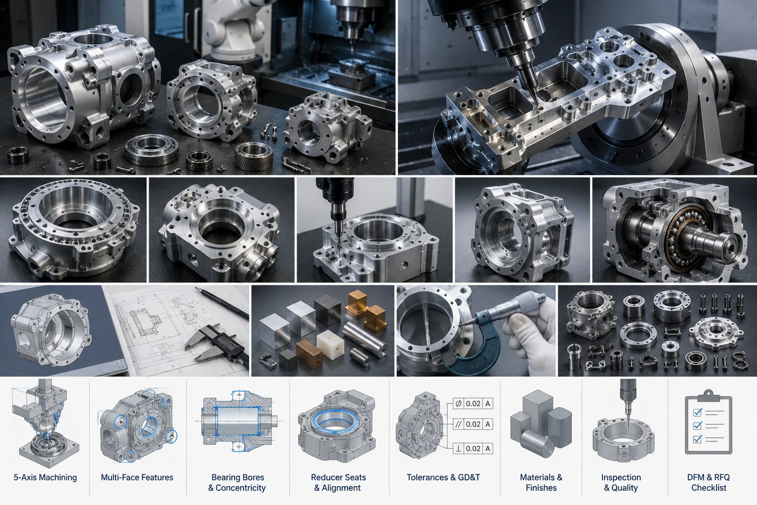
Why 5-Axis Machining for Robot Housings Matters
5-axis machining for robot housings becomes valuable when a part combines compact geometry, tight alignment, multiple functional faces, and difficult inspection requirements.
A robot actuator housing may need to locate the motor, bearing, shaft, encoder, brake, wiring channel, and cover face in one compact body. A reducer housing may need to control a harmonic reducer seat, output bearing bore, bolt circle, dowel holes, grease cavity, sealing groove, and output flange interface. These features rarely sit conveniently on one flat face.
This is where 5-axis machining can help. Compared with repeated 3-axis setups, 5-axis machining can access more faces with fewer re-clamping operations. That reduces datum transfer risk and makes it easier to control the relationship between bores, mounting faces, and angled features.
The robotics market also explains why housing accuracy is becoming more important. The International Federation of Robotics reported 4,281,585 industrial robots operating in factories worldwide in 2023, a 10% increase. IFR also reported 541,302 new industrial robot installations in 2023. More robots in real production means more joint modules, actuator assemblies, and reducer housings must run reliably under repeated motion.
For complex housings with multi-face features, Boona 5-axis CNC machining capability is especially relevant for prototypes, validation builds, and low-volume robot joint components.
Robot Actuator and Reducer Housings Are Difficult to Machine
Robot actuator housing machining is challenging because the housing must hold several functional systems in alignment. It may support a motor, bearing stack, output shaft, encoder, brake, cable exit, sensor cover, and thermal path. Each feature has its own tolerance requirement, but the relationship between features often matters more than any single dimension.
Robot reducer housing machining creates similar difficulty. A reducer housing must locate the reducer seat, output bearing bore, input shaft path, bolt circle, dowel holes, cover face, sealing groove, and sometimes grease cavities or lubrication channels. If the reducer seat is not flat or the bore axis is not controlled, the assembly may create uneven loading, abnormal noise, vibration, or reduced reducer life.
The hardest robot housings usually include:
- large bearing bores
- deep internal pockets
- thin-wall sections
- circular reducer seats
- recessed bolt patterns
- multiple angled faces
- cable passages
- sealing grooves
- dowel pin locations
- tight clearance areas
- compact motor and encoder interfaces
A robot housing may look like a protective shell, but in a precision joint it behaves more like an alignment fixture. That is why machining strategy, datum planning, workholding, finishing, and inspection all need to be considered before quoting.
How 5-Axis CNC Machining Improves Housing Accuracy
5-axis CNC machining for robotics helps because many robot housings need accurate features on several sides. A traditional 3-axis process may require one setup for the main face, another setup for side features, another for angled surfaces, and another for deep or recessed details. Every re-clamp creates another chance for datum transfer error.
5-axis machining allows the tool or part to rotate so the cutter can reach complex areas more directly. This can improve tool access, reduce long-tool deflection, improve surface finish on angled faces, and keep multiple features related to a more stable datum strategy.
That does not mean 5-axis machining automatically makes every part better. A poor fixture, unclear datum scheme, weak toolpath strategy, or incomplete inspection plan can still create problems. The value comes from combining 5-axis machine access with good engineering judgment.
| Factor | 3-Axis Machining | 5-Axis Machining |
|---|---|---|
| Multi-face access | Often needs several setups | Reduces re-clamping |
| Datum transfer | Higher risk across setups | Better feature relationship |
| Deep pockets | May require long tools | Allows better tool angles |
| Angled features | Needs special fixtures | Easier direct access |
| Compact housings | More setup planning | Better for complex geometry |
| Low-volume batches | Setup variation can grow | More consistent process control |
For housings with bearing bores, reducer seats, motor faces, and side ports, fewer setups can be a major advantage. The part does not just need accurate surfaces; it needs accurate relationships between those surfaces.
Key Features in CNC Machined Actuator Housings
A CNC machined actuator housing must support both structure and motion.
In many robot joints, the actuator housing locates the motor, supports a bearing, guides a shaft, protects the encoder, routes cables, and connects to the next mechanical structure. If the housing lacks stiffness, the joint may vibrate. If the bearing bore is not accurate, the shaft may not rotate smoothly. If the encoder area lacks stability, feedback quality can suffer.
Typical actuator housing features include:
- motor mounting face
- bearing bore
- shaft bore
- encoder pocket
- dowel pin holes
- threaded holes
- cable exit
- cover sealing face
- heat dissipation surface
- brake or sensor mounting area
The motor mounting face often needs flatness and perpendicularity control. The bearing bore may require a controlled fit, roundness, and surface finish. Dowel holes should support repeatable assembly. Cable exits need smooth deburring to prevent wire damage.
Material choice depends on the design. Aluminum 6061 works well for many prototype actuator housings because it machines cleanly, keeps weight low, and accepts anodizing. Aluminum 7075 can support compact or higher-load housings. Stainless steel inserts may help in wear or thread-critical locations. Engineering plastics can work for covers, insulation, or cable routing features.
Boona precision machining service is a better fit when actuator housing performance depends on bores, dowels, mating faces, and controlled GD&T rather than simple external shape.
Key Features in CNC Machined Reducer Housings
A CNC machined reducer housing must locate the reducer accurately and transfer load without distortion.
Robot joints may use harmonic reducers, cycloidal reducers, planetary gearboxes, or custom compact gear assemblies. Each reducer type has its own mounting pattern, output interface, and load path. The housing must support these features while keeping the bore axis, reducer seat, and output interface aligned.
Critical reducer housing features often include:
- reducer mounting seat
- output bearing bore
- output flange interface
- input shaft alignment
- bolt circle
- dowel holes
- grease cavity
- sealing groove
- cover face
- inspection datum surfaces
Poor machining can create uneven reducer loading, output runout, abnormal noise, vibration, assembly stress, and premature reducer wear. Even when the reducer itself is high quality, the surrounding housing can limit performance.
5-axis machining helps when the reducer housing includes recessed areas, angled faces, multi-side bolt patterns, and compact geometry. It can also reduce the need for special fixtures when multiple functional faces must be machined relative to the same datum strategy.
For robot teams, the most practical question is not whether the housing looks complex. The real question is whether the bearing bore, reducer seat, motor face, dowel holes, and flange interface all work together after assembly. That is where machining and inspection planning become critical.
Bearing Bores, Concentricity, and Datum Control
Bearing bores often decide whether a robot actuator or reducer housing runs smoothly.
The bore diameter matters, but it is only one part of the story. Roundness, bore axis alignment, perpendicularity to the mounting face, coaxiality with another bore, shoulder depth, surface finish, and true position may all affect joint performance. For a reducer housing, the relationship between the output bearing bore and reducer seat can matter more than either feature measured alone.
Practical tolerances depend on the bearing, reducer, housing size, material, and assembly method. Selected functional features may require tolerances around ±0.02 mm to ±0.05 mm. Bearing bores may use H7-style fits where the design requires controlled assembly. Sealing areas or sliding features may also need specified roughness.
A clear datum strategy makes inspection and machining easier. The drawing should define the primary mounting face, bore axis, secondary dowel reference, and any functional interface that controls assembly. Vague datums force the supplier to guess, and guessed datums usually create quoting risk.
ISO 9283 covers performance criteria and related test methods for manipulating industrial robots, including accuracy and repeatability. It does not tell a machinist how to cut a bore, but it reinforces a useful engineering idea: robot performance depends on controlled, measurable relationships.
💡 Pro Tip: Do not only tolerance the bore diameter. For robot actuator and reducer housings, the relationship between the bore axis, mounting face, reducer seat, and dowel holes is often more important than one isolated size dimension.
Materials and Finishes for Robot Actuator and Reducer Housings
Material selection should follow housing function.
Aluminum 6061 is a common choice for robot actuator and reducer housings because it offers good machinability, low weight, reasonable cost, and easy anodizing. It works well for prototypes, development builds, covers, joint housings, and general-purpose robot structures.
Aluminum 7075 provides higher strength and better strength-to-weight performance. It makes sense for compact housings, high-load robot joints, lightweight actuator modules, and parts where stiffness matters more than material cost. It may require finishing for corrosion protection.
Stainless steel fits inserts, shafts, wear areas, threaded features, and high-load interfaces. It machines slower and adds weight, so it should solve a specific problem. PEEK, POM, and nylon may support insulation, cable guides, covers, wear pads, or low-friction features. Copper and brass appear in thermal, grounding, bushing, or fitting applications.
Boona CNC machining material list can help engineers compare metals and plastics before sending an RFQ.
Finishing must protect the housing without damaging critical fits. Anodizing, black anodizing, hard anodizing, bead blasting, passivation, black oxide, nickel plating, and polishing all have useful roles. But coatings can affect bearing bores, reducer seats, and sliding fits. Tight bores may need masking, post-finish machining, or clear drawing notes.
Deburring also matters. Cable exits, internal pockets, threaded holes, sealing grooves, and hand-access edges should not have sharp burrs. A clean finish can prevent assembly damage and improve serviceability.
Tolerances, GD&T, and Inspection Planning
Robot housing drawings should control function, not every visible surface.
Critical features often include bearing bores, reducer seats, motor mounting faces, shaft holes, dowel holes, output flange interfaces, sealing grooves, encoder mounting areas, and cover faces. These features affect assembly, motion, sealing, feedback, and service life.
GD&T can help when it describes actual function. True position can control dowel holes and bolt patterns. Flatness can protect motor and reducer faces. Perpendicularity can control shaft and bore alignment. Runout and concentricity may matter for rotating features. Profile tolerance may help on complex surfaces when the shape supports assembly or sealing.
The mistake is applying tight tolerances everywhere. External cosmetic faces, clearance pockets, non-functional reliefs, and simple cover surfaces can often use general tolerances. Over-tolerancing increases cost, inspection time, and quoting uncertainty.
| Housing Feature | Tolerance Priority | Why It Matters |
| Bearing bore | High | Controls rotation and load support |
| Reducer seat | High | Controls reducer alignment |
| Motor mounting face | High | Controls motor position |
| Dowel holes | High | Controls repeatable assembly |
| Sealing groove | Medium to high | Controls sealing reliability |
| Cable passage | Medium | Affects routing and service |
| Outer cosmetic face | Low | Usually not motion-critical |
Inspection should match risk. A housing prototype may only need key dimensions checked. A pilot batch for robot joint modules may need CMM reports, bore measurements, pin gauge checks, thread inspection, surface roughness testing, and visual inspection. Boona quality control process is relevant when buyers need dimensional reports for critical machined robot housings.
Mini Case Study: Compact Robot Joint Housing
A robotics team was developing a compact joint module for a small industrial arm. The housing included a motor mounting face, harmonic reducer seat, output bearing bore, encoder pocket, cable exit, dowel holes, and cover face.
The first prototype used multiple 3-axis setups. The part looked acceptable after machining, but assembly revealed small alignment problems between the reducer seat and output bearing bore. The team also needed extra inspection time because several features had to be checked across transferred datums.
The revised approach used a 5-axis machining strategy. The fixture referenced the main datum face, roughing removed most material, and finish machining controlled the bearing bore, reducer seat, and related interfaces after the part stabilized. Several side features were machined with fewer re-clamping steps, which reduced datum transfer risk.
The goal was not to claim that 5-axis machining made the housing “perfect.” The real improvement came from a better process plan: clearer datum control, better tool access, fewer setups, finish machining on critical bores, and focused inspection on the features that affected assembly.
For the pilot batch, the team saw more consistent assembly and less manual fitting. That is where 5-axis machining often creates value: not only in cutting complex geometry, but in reducing hidden alignment problems before they reach the robot build.
DFM Tips for 5-Axis Robot Housing Machining
Good DFM reduces cost without weakening the housing.
Start with datums. Define the main mounting face, bore axis, dowel references, and inspection surfaces before the design becomes too detailed. If the datum scheme changes late, the whole machining and inspection plan may need revision.
Keep material around bearing bores, reducer seats, threaded holes, and load paths. Weight reduction is useful, but aggressive hollowing near functional interfaces can create distortion or stiffness problems. Deep pockets should have tool-friendly radii. Very thin walls should be avoided unless the design truly needs them.
Use standard threads where possible. Avoid hidden undercuts. Check tool access for recessed holes and angled features. Separate cosmetic surfaces from functional faces. Consider finish buildup before assigning tight dimensions. Leave enough inspection access for CMM probes, bore gauges, and pin gauges.
| Cost Driver | Why It Raises Cost | DFM Fix |
| Deep internal pockets | Long machining time | Add larger radii and reduce depth |
| Thin walls | Deformation risk | Keep practical wall thickness |
| Tight tolerance everywhere | More inspection | Control only functional features |
| Small internal corners | Requires small tools | Use larger cutter radii |
| Multiple datum faces | Setup risk | Simplify datum scheme |
| Hard anodizing on bores | Fit risk | Mask or define post-finish size |
5-axis machining is not automatically cheaper than 3-axis machining. It can cost more per machine hour. But when it reduces setups, prevents rework, improves access, and stabilizes feature relationships, the total manufacturing cost can be lower for complex robot housings.
RFQ Checklist for Robot Actuator and Reducer Housings
A 3D model shows geometry. It does not explain how the housing works inside the robot joint.
For accurate quoting, buyers should provide:
- STEP, IGES, or X_T CAD file
- 2D drawing for critical features
- material requirement
- quantity
- prototype, validation, or production stage
- actuator or reducer type
- bearing type and fit
- motor interface details
- reducer model or mounting pattern
- critical tolerances
- GD&T requirements
- finish and color
- masking requirements
- inspection report needs
- lead time target
- assembly concerns
- sealing or cable routing requirements
A short function note helps the supplier understand the part:
“Robot reducer housing, aluminum 7075, 10 pcs, black anodized, harmonic reducer seat and output bearing bore critical, CMM report required for bore axis, dowel holes, and mounting face.”
That note gives useful context. The part is not just a round aluminum housing. It is a reducer alignment body with bearing, dowel, and mounting face requirements. Better input usually leads to better DFM feedback, more accurate pricing, and fewer revisions after machining.
Related Reading
For broader robot arm hardware planning, read our guide to robot arm components machining. If your project involves compact actuators and structural joint parts for humanoid platforms, review our article on humanoid robot parts machining. For end-of-arm tooling interfaces, the guide to CNC machining for robot grippers and end effectors provides useful context.
Conclusion: 5-Axis Machining for Robot Housings Needs Function-First Planning
5-axis machining for robot housings is most valuable when the housing must control several functional relationships at once: bearing bore to reducer seat, motor face to shaft axis, dowel holes to mounting datum, and sealing grooves to cover faces.
Robot actuator and reducer housings are not simple covers. They influence motion smoothness, reducer life, vibration, heat, assembly repeatability, and long-term reliability. Successful machining requires more than a capable machine. It needs a clear datum strategy, practical tolerances, correct material selection, finishing awareness, inspection planning, and DFM feedback before production starts.
For prototypes, pilot builds, and low-volume robot joint modules, 5-axis machining gives engineering teams a practical way to produce compact, complex, and functional housings from real materials.
If you are developing robot actuator housings, reducer housings, gearbox housings, bearing carriers, or compact robot joint parts, send your CAD files, drawings, and application notes to Boona 5-axis CNC machining team. We can help review materials, tolerances, datum strategy, finishing, inspection, and DFM before machining begins.
FAQs About 5-Axis Machining for Robot Housings
Why is 5-axis machining used for robot actuator housings?
5-axis machining helps access multiple faces, reduce re-clamping, control feature relationships, and machine compact actuator housing geometry with better consistency. It is especially useful when motor faces, bearing bores, dowel holes, cable exits, and encoder pockets must stay aligned.
What features are critical in robot reducer housing machining?
Critical features include reducer seats, bearing bores, output flange interfaces, dowel holes, bolt circles, shaft holes, sealing grooves, cover faces, and inspection datums. These features affect reducer alignment, output runout, vibration, noise, and assembly repeatability.
What materials are used for robot actuator and reducer housings?
Aluminum 6061 is common for general housings and prototypes. Aluminum 7075 is used for high-strength lightweight housings. Stainless steel may be used for inserts, shafts, and wear features. PEEK, POM, nylon, copper, and brass support special insulation, friction, thermal, or electrical needs.
What tolerances matter most for robot housing machining?
Bearing bore diameter, bore axis alignment, reducer seat flatness, dowel hole position, motor face perpendicularity, sealing groove control, and output flange runout usually matter most. Cosmetic faces and non-functional pockets can often use wider general tolerances.
Is 5-axis machining always better than 3-axis machining?
No. Simple housings may be machined well with 3-axis equipment. 5-axis machining becomes more valuable when the housing has multi-face features, angled geometry, recessed holes, tight feature relationships, compact design, or reduced setup risk requirements.
What should buyers include in an RFQ for robot housings?
Buyers should provide CAD files, 2D drawings, material, quantity, actuator or reducer model, bearing fit, motor interface details, critical tolerances, GD&T, finish, masking needs, inspection report requirements, lead time, and assembly concerns.


