
A robot build rarely moves from CAD to stable production in one clean step. The first bracket may need a hole pattern change. A gripper adapter may pass fit testing but wear around its mounting threads after repeated service. A sensor plate may look simple, then require tighter flatness after assembly testing. When every revision forces a large batch order, teams waste budget and delay validation. That is why no MOQ CNC machining matters for custom robot parts: teams can machine one part, test it, revise it, and scale only when the design is ready.
Robotics demand remains strong across industrial and service applications. According to the International Federation of Robotics, 542,000 industrial robots were installed worldwide in 2024, keeping annual installations above 500,000 units for the fourth consecutive year. Asia accounted for 74% of new deployments in 2024. IFR also reported that professional service robot sales reached almost 200,000 units in 2024, up 9% year over year.
For robotics startups, automation integrators, R&D labs, and OEM engineering teams, flexible manufacturing is not a convenience. It helps engineering teams reduce risk, validate function, and move from first prototype to pilot production without locking into unnecessary inventory.
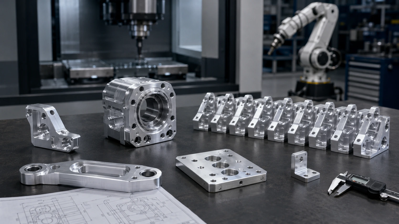
What No MOQ Means for Custom Robot Parts
No MOQ means no minimum order quantity. A team can order one prototype bracket, three revised gripper plates, ten actuator mounts, or a small pilot batch without meeting a fixed quantity threshold. For robotics projects, this flexibility often matters more than a small unit-price reduction on an unproven design.
Robot hardware changes quickly because each part connects to a larger motion system. A sensor mount depends on camera angle and cable clearance. A robot wrist adapter must match both the robot flange and the tool interface. A gripper base may need dowel holes, threaded inserts, vacuum ports, or contact surfaces that only make sense for one production line.
Traditional MOQ purchasing works better after a design has stabilized. It can reduce cost at volume, but it raises risk when a team still needs to test fit, load, surface finish, and assembly behavior. No MOQ machining lets engineers validate before committing to a larger batch.
| Factor | No MOQ CNC Machining | Traditional MOQ Manufacturing |
|---|---|---|
| Starting quantity | 1 piece or small batch | Often dozens to hundreds |
| Best stage | Prototype, revision, pilot build | Mature production |
| Design flexibility | High | Lower after order release |
| Upfront cost | Lower | Higher |
| Revision risk | Easier to control | Expensive if geometry changes |
| Best-fit parts | Custom brackets, EOAT plates, joints, housings | Stable standardized components |
This approach fits robotics because many robot parts remain custom even after the product leaves the lab.
A Practical Workflow from First Prototype to Pilot Production
A practical no MOQ workflow starts with CAD review, not machining. The customer sends 3D files, 2D drawings, material notes, and application requirements. A good supplier checks wall thickness, tool access, internal radii, hole depths, thread design, tolerance needs, surface finish, and inspection points before the first chip is cut.
The first CNC prototype usually includes one to five pieces. At this stage, the team checks more than shape. Engineers need to validate assembly fit, motor mounting, bearing alignment, cable routing, gripper clearance, flatness, stiffness, and repeated motion behavior. A real machined part can expose problems that a plastic print or visual model may hide.
After testing, the design may change. The team may move a hole, add a rib, change material, adjust port location, increase thread engagement, or tighten one functional tolerance. With no MOQ, the next revision can stay small and focused.
Once the design passes testing, the order may grow to 20, 50, or 100 pieces. The process then shifts from fast learning to repeatability: consistent material, stable setup, defined inspection, and controlled finishing.
Why CNC Machining Fits No MOQ Robot Parts
CNC machining fits robotics because robot components often need real engineering materials and accurate functional features. A 3D printed model can help check packaging, but CNC machining proves performance when a part must carry load, hold alignment, resist wear, or survive repeated service.
Common CNC machined robot features include bearing bores, dowel pin holes, motor mounting faces, gearbox interfaces, threaded holes, vacuum channels, sealing surfaces, sensor pockets, and flat datum faces. These details affect how the robot moves, grips, aligns, and repeats.
Material flexibility also supports development. A team may start with aluminum 6061 for speed and cost, then move selected parts to aluminum 7075 for higher load. Stainless steel may fit shafts, pins, or wear surfaces. POM, nylon, ABS, PC, and PEEK may support insulation, weight reduction, or low-friction requirements. Boona’s CNC machining material options can help teams compare practical metals and plastics before RFQ.
For prototype and low-volume robot parts, Boona’s precision CNC machining services support machined metal and plastic components with functional tolerances and surface finishing. When parts include multiple angled faces, deep pockets, or compact actuator geometry, 5-axis CNC machining can reduce setups and improve feature alignment.
💡 Pro Tip: Request DFM feedback before the first prototype reaches the machine. The cheapest time to fix a tolerance, wall thickness, port location, or tool-access problem is before machining starts.
Common Robot Parts Made with No MOQ CNC Machining
No MOQ CNC machining works best for robot parts that combine custom geometry with functional accuracy. These parts often cannot come from catalog hardware because they must match a specific robot structure, actuator layout, payload, tool interface, or automation cell.
Common examples include robot arm links, joint plates, bearing housings, actuator mounts, gearbox housings, camera brackets, LiDAR mounts, sensor plates, cable-routing blocks, end-effector adapters, gripper fingers, vacuum tool mounts, and custom fixture plates.
Robot arm components need stiffness, low weight, and accurate alignment. A small error around a bearing bore or motor face can reduce repeatability. Boona’s article on robot arm components machining explains how joints, links, brackets, and bearing seats support motion accuracy.
End-of-arm tooling has a different set of risks. The part may need controlled contact geometry, vacuum channels, dowel holes, replaceable wear surfaces, or sensor mounts. Boona’s guide to CNC machining for robot grippers and end effectors covers these EOAT requirements in more detail.
A flexible no MOQ approach lets teams order only the parts needed for the next test, not a warehouse full of components tied to an unfinished design.
Material Selection for Prototype and Production Robot Parts
Material selection should follow the job of the part. Early prototypes often use aluminum 6061 because it machines cleanly, keeps cost reasonable, and works well for brackets, covers, plates, housings, and test fixtures. Aluminum 7075 suits parts that need higher strength, especially compact arm links, actuator interfaces, gripper bases, and high-load mounting structures.
Stainless steel works well when the part needs wear resistance, corrosion resistance, threaded durability, or higher mass. Shafts, pins, bushings, contact plates, and heavy-duty fixtures often use stainless steel, though the material can increase machining time and part weight.
Engineering plastics solve different problems. POM works well for low-friction parts. Nylon can reduce weight and absorb impact. PEEK handles heat, insulation, chemical exposure, and demanding functional environments. ABS and PC may fit covers, housings, and non-load-bearing prototype components.
A prototype does not always need the final material, but the team should understand what each test proves. A 6061 part can validate assembly quickly. A later 7075, stainless steel, or PEEK version may validate load, wear, insulation, or thermal behavior. For broader robotics material planning, Boona’s article on CNC machining for robotics gives useful context on custom precision robot parts.
Tolerance, DFM, and Inspection Before Scaling
A robot part does not need tight tolerance everywhere. It needs tight tolerance where function depends on it. Bearing bores, dowel holes, motor mounting faces, reducer seats, sealing faces, and tool interface patterns often control robot performance. Cosmetic pockets, clearance holes, and outside profiles may not require the same level of precision.
For many robot parts, functional tolerances in the ±0.02 mm to ±0.05 mm range may apply to selected features. Applying that tolerance across every dimension increases cost and inspection burden without improving the assembly. A better drawing separates critical-to-function features from general-machined features.
DFM review should check internal radii, pocket depth, thin walls, thread engagement, workholding faces, tool access, surface finish requirements, and post-processing allowance. Anodizing, hard anodizing, bead blasting, brushing, electroless nickel plating, and passivation can affect final appearance or dimensions.
Inspection planning becomes more important when a project moves from one part to a small batch. For a prototype, the team may check only the critical features. For a pilot build, the supplier should define repeatable inspection points, measurement tools, sampling approach, and packaging protection. This prevents minor variation from becoming an assembly-line problem.
Prototype vs Pilot Production: What Changes?
The machine may be the same, but the manufacturing mindset changes after the prototype stage. During prototyping, the team wants speed, practical feedback, and room to change. During pilot production, the team needs repeatability, documentation, cost control, and consistent finish.
| Requirement | Prototype Stage | Pilot / Low-Volume Production |
|---|---|---|
| Typical quantity | 1–5 pieces | 10–500+ pieces |
| Main goal | Fit, function, early testing | Repeatability and stable process |
| Design status | Still changing | Mostly frozen |
| Cost focus | Speed and flexibility | Unit cost and consistency |
| Inspection focus | Key features checked | Defined inspection plan |
| Finishing | May be experimental | More consistent and controlled |
Before moving into low-volume robot parts manufacturing, confirm material grade, finish, critical tolerances, thread requirements, inspection dimensions, and packaging needs. Small details such as countersink depth, anodizing allowance, dowel pin fit, or thread insert type can create problems when multiplied across a batch.
This stage also gives teams a chance to lower cost without weakening the part. A supplier may recommend larger internal radii, simplified setups, standard drill sizes, better fixture surfaces, or relaxed tolerances on non-critical geometry.
Application Example: From One EOAT Adapter Prototype to a Pilot Batch
A practical no MOQ scenario often appears in end-of-arm tooling. A robotics integrator may need a custom EOAT adapter plate for a packaging line, but the final gripper layout is not confirmed yet. The first order may include only one CNC machined aluminum plate to check the robot flange pattern, vacuum port position, dowel alignment, and clearance around pneumatic fittings.
During the first line trial, the prototype fits the robot wrist, but two issues appear. The vacuum fitting sits too close to a cable clamp, and repeated tool changes begin to wear the aluminum threads around one mounting point. The flatness of the suction interface also needs tighter control because a 0.05–0.10 mm gap can reduce vacuum stability on lightweight packaging materials.
Instead of ordering a full batch too early, the team revises the plate before production. The second version adds steel threaded inserts, moves the vacuum port by 6 mm, and tightens the sealing face flatness requirement to 0.03 mm. After the revised prototype passes the line trial, the team orders a pilot batch of 40 pieces for multiple robot cells.
This example shows why no MOQ CNC machining is valuable. The team validates the functional design first, fixes real assembly and service issues, and scales only after the part performs correctly on the production line.
Choosing the Right Manufacturing Partner for No MOQ Robot Parts
A supplier for no MOQ robot parts should offer more than available machine time. Robotics hardware requires application understanding. Bearing bores, dowel holes, motor faces, thread quality, flatness, and surface finish all affect how the robot assembles and performs.
Look for process coverage that matches the project: 3-axis CNC milling, 5-axis machining, CNC turning, metal and plastic machining, surface finishing, and inspection support. A capable supplier should also understand common robotics materials such as aluminum 6061, aluminum 7075, stainless steel 304/316, brass, copper, titanium, POM, nylon, PC, ABS, and PEEK.
DFM support matters most when the design moves from a prototype to a batch. A good supplier should flag hard-to-machine corners, risky thin walls, unnecessary tight tolerances, deep pockets, weak threads, finishing conflicts, and unclear drawings before production starts.
Communication also matters. Robotics projects change quickly. A supplier that can review CAD, confirm requirements, and support small revisions helps engineering teams move faster without losing control over quality.
Final Recommendation: Build, Test, Revise, Then Scale
No MOQ CNC machining gives robotics teams a practical path from first sample to pilot production. The first prototype proves fit. The next revision improves function. A small batch checks repeatability. Pilot production supports real deployment before larger-volume manufacturing makes sense.
The best results come from matching quantity, material, tolerance, finish, and inspection to the development stage. Order enough parts to answer the next engineering question, not enough to fill inventory before the design is proven. Use CNC machining to validate real materials, functional interfaces, threads, bores, sealing faces, and assembly behavior.
For robot parts, flexibility often creates more value than early volume pricing. A no MOQ approach lets teams avoid outdated inventory, fix problems sooner, and scale only after the design earns confidence. That makes it especially useful for robotics startups, automation integrators, R&D teams, and OEM programs working with custom hardware.
FAQs
Can I order only one custom robot part?
Yes. No MOQ CNC machining allows teams to order one custom robot part for prototype testing, then increase quantity after the design passes fit, function, and assembly testing.
Is CNC machining suitable for both prototype and production robot parts?
Yes. CNC machining works well for functional prototypes, pilot builds, and low-volume production robot parts because it supports real engineering materials, accurate features, and repeatable quality.
What robot parts can be CNC machined with no MOQ?
Common examples include robot arm links, actuator mounts, EOAT adapter plates, gripper fingers, sensor brackets, camera mounts, gearbox housings, cable-routing blocks, and custom fixture plates.
What materials are best for robot parts?
Aluminum 6061 works well for general brackets, housings, covers, and prototype frames. Aluminum 7075 suits high-load links, actuator mounts, and gripper bases. Stainless steel, PEEK, POM, nylon, ABS, and other materials may fit specific wear, insulation, weight, or strength requirements.
How can I reduce the cost of custom robot parts?
Use practical tolerances, simplify setups, avoid unnecessary deep pockets, standardize hole sizes, choose the right material, confirm surface finish early, and ask for DFM feedback before production.
When should I move from prototype to pilot production?
Move to pilot production after the part passes fit, function, assembly, and motion testing. Before scaling, confirm final material, tolerances, finish, inspection dimensions, threaded features, and packaging requirements.
Get No MOQ CNC Machining for Custom Robot Parts
Whether you need one prototype robot bracket, a revised EOAT adapter plate, or a pilot batch of precision robot components, Boona supports no MOQ CNC machining for custom robotics hardware. Send your CAD files, drawings, and application notes to Boona’s CNC machining for robotics team to get DFM feedback and a quote for custom robot parts.


