
A designer specifies black anodizing across an aluminum diagnostic enclosure, then discovers that the same enclosure must provide a low-resistance grounding path between a connector shell and the chassis. The exterior finish is appropriate for the product, yet the coating changes an electrical interface that the system depends on.
The design review quickly expands. Connector openings must align with PCB-mounted hardware, a perimeter gasket needs consistent compression, a thermal pad has to contact a power component, and a heavily pocketed base must remain stable after machining.
These interactions define medical device aluminum enclosure machining. A successful enclosure coordinates structural, thermal, electrical, sealing and cosmetic requirements within the same component.
For a CNC aluminum medical device enclosure, the most important dimensions are often relationships between features rather than isolated dimensions on the drawing.
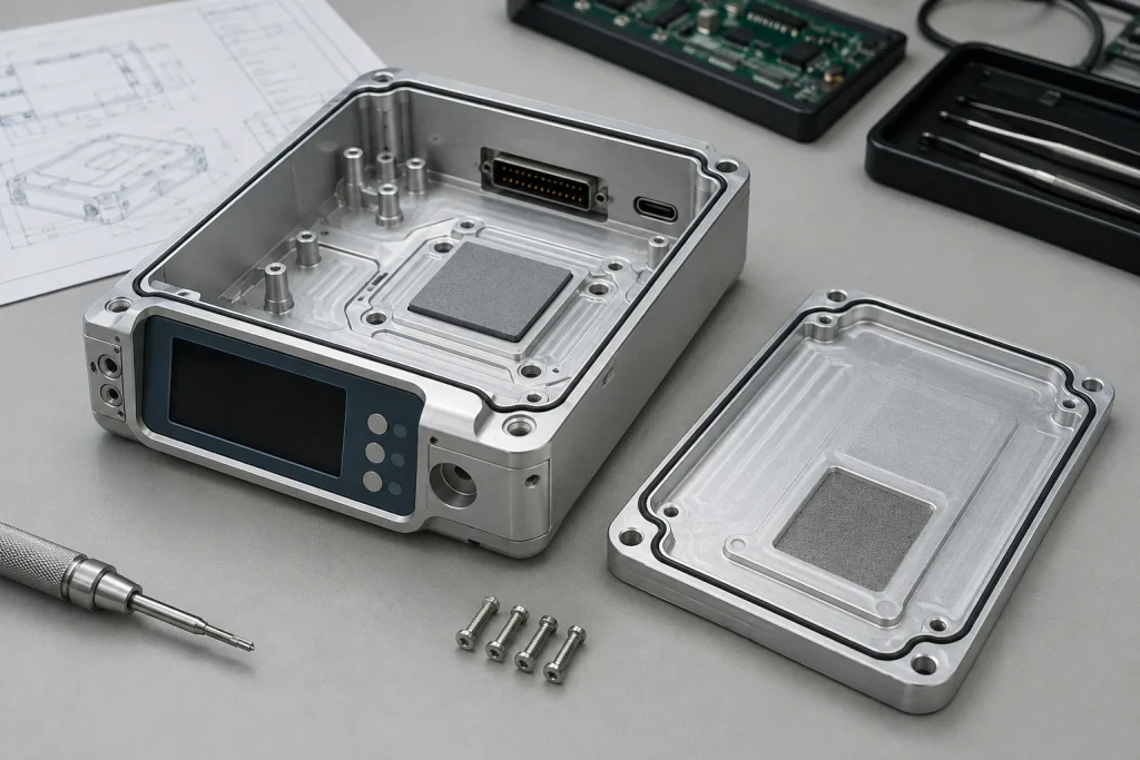
Medical Device Aluminum Enclosure Machining: What Makes It Different?
A machined medical device housing may serve as the structural reference for nearly every internal subsystem.
PCB mounting bosses establish board position. Connector openings must align with hardware attached to that board. Sensor apertures can control an optical or measurement axis, while display openings and button features must remain aligned with user-interface components.
The enclosure may also carry heat away from electronics, provide conductive paths for shielding and grounding, and create the rigid half of a gasketed sealing interface.
Exterior geometry adds another design layer. Visible surfaces may require consistent bead blasting or anodizing, while nearby functional surfaces require controlled flatness, masking or bare-metal electrical contact.
This is why tolerance strategy matters. A connector opening can satisfy its coordinate dimensions from an exterior wall and still sit incorrectly relative to the PCB connector.
A stronger drawing establishes functional datums around the assembled system. The PCB seating plane, a locating edge and a defined tertiary feature can become the reference structure for ports, sensors and display openings.
For a broader look at aluminum components across medical equipment, see BOONA guide to CNC machining aluminum parts for medical devices.
Choosing Aluminum for a Medical Device Enclosure
A 6061 aluminum medical enclosure is frequently considered for machined diagnostic and electronic equipment because 6061-T6 or T651 offers a practical combination of machinability, structural capability, corrosion resistance and finishing flexibility.
The drawing should specify the actual alloy and temper. “Medical-grade aluminum” is too vague to define an enclosure material.
Higher-strength 7075 may be appropriate where structural load genuinely drives the design. Its additional strength does not automatically improve a housing whose critical requirements involve flatness, heat transfer, sealing or surface treatment.
Manufacturing architecture can also change the alloy decision. A machined monolithic body, extrusion-based housing and folded sheet-metal cabinet solve different problems.
Typical architectures include:
- Machined base plus removable cover
- One-piece deeply pocketed housing
- Extruded body with machined end plates
- Sheet-metal chassis with machined brackets
- Hybrid enclosure using several manufacturing processes
Material selection should follow structural load, thermal behavior, corrosion exposure, finishing requirements and manufacturing geometry together.
For many compact instruments, the ability to integrate bosses, sealing grooves, thermal interfaces and multi-face openings into one rigid enclosure is the main reason CNC machining enters the design discussion.
Thin Walls and Distortion in Medical Device Aluminum Enclosure Machining
An enclosure often starts as substantial stock and finishes with most of the interior removed. That geometry creates one of the biggest manufacturing risks: distortion.
As large pockets are machined, residual stresses within the stock redistribute. Flexible walls can also deflect under cutting force or clamping. A base that appears flat while restrained in a fixture may move after release.
A 2025 peer-reviewed study on micro-milling thin-wall Al6061-T6 investigated walls only 50 µm thick, 1 mm high and 10 mm long. Within that specific experiment, ANOVA attributed 87.36% of the measured wall-deformation influence to feed rate.
Those dimensions are far smaller than a conventional medical enclosure and should never be treated as a recommended housing wall thickness. The research is useful because it demonstrates how strongly flexible aluminum geometry can respond to machining conditions.
Enclosure DFM should consider:
- Balanced material removal
- Practical wall transitions
- Ribs where structurally justified
- Accessible clamping areas
- Generous internal corner radii
- Roughing and finishing sequence
- Inspection after fixture release
💡 Pro Tip: State the condition in which flatness applies. A free-state enclosure base, a bolted base and an assembled housing can produce different measurements.
Datums, PCB Alignment and Repeated Assembly
Functional datums should follow the parts that the enclosure actually locates.
Consider a PCB-mounted connector. If the connector cutout is dimensioned from an unrelated cosmetic side wall while the PCB bosses reference another surface, the two tolerance chains can drift independently.
A more useful structure might use:
- PCB seating surface as the primary datum
- Board locating edge as the secondary datum
- Locating hole or reference feature as the tertiary datum
Connector openings, display windows and sensor apertures can then reference the same functional system.
Threads and inserts add another consideration. Internal PCB screws may see very few assembly cycles, while battery compartments, calibration covers and service panels can experience repeated removal.
The design team should decide whether tapped aluminum, a threaded insert or another fastening method fits the expected service condition.
Finishing sequence belongs on the drawing as well. If anodizing affects a precision bore, threaded feature or electrical contact, the specification should identify whether dimensions apply before or after finishing and which surfaces require masking.
This prevents the machine shop, finishing supplier and assembly team from interpreting the same feature three different ways.
Gasket Grooves and Ingress Protection
Portable diagnostic instruments, analyzers and monitoring equipment may require protection against dust, spills or cleaning liquids.
IEC 60529 and the IP classification system define degrees of enclosure protection against solid objects and liquids.
For the machined housing, sealing performance can depend on several interacting features:
- Gasket groove width and depth
- Sealing-land geometry
- Cover flatness
- Corner transitions
- Screw locations
- Connector interruptions
- Base-to-cover alignment
A groove that meets its local dimensions can still produce uneven compression if the cover bows after machining or fasteners load the perimeter unevenly.
Ports deserve particular attention because connectors, cable entries and removable access panels interrupt the sealing boundary.
Machining should therefore follow a gasket and enclosure design already defined by the product engineering team.
An IP designation applies to the assembled product configuration. CNC machining can create the specified sealing geometry, while the final rating depends on the gasket, connectors, covers, fasteners, assembly condition and validation testing.
The component drawing should communicate the geometry and surface requirements needed to support that verification strategy.
Thermal Management, EMC and Grounding Interfaces
Aluminum can allow the enclosure to function as both a structural chassis and part of the thermal path.
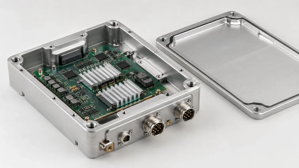
A power device, processor, optical module or other heat source may transfer energy through a thermal interface material into a machined enclosure pad. Relevant features can include flat contact areas, internal heat-spreading structures and external fins where the thermal design requires them.
Thermal-interface requirements should be defined separately from cosmetic geometry. A functional contact pad may need control over flatness and surface condition that provides no benefit on a decorative wall.
EMC creates a different set of functional interfaces. IEC 60601-1-2:2014+A1:2020 specifies requirements and tests related to electromagnetic disturbances for medical electrical equipment and systems.
An enclosure can contribute through:
- Conductive seams
- Grounding studs
- Connector-shell contact
- Conductive gasket interfaces
- Controlled cover contact
- Aperture geometry
Surface finishing becomes critical here. Anodic oxide is electrically insulating compared with bare aluminum, so electrical bonding areas may require controlled masking or another defined contact strategy.
EMC performance belongs to the complete electrical system. Enclosure machining supports specified mechanical interfaces; complete-device verification establishes whether the design meets its applicable EMC requirements.
Anodizing, Cleaning and Surface-Finish Boundaries
An anodized aluminum medical enclosure may use its finish to improve corrosion resistance, wear behavior and exterior appearance.
The finishing specification should distinguish cosmetic areas from functional interfaces. A visible panel, precision bore, threaded hole, gasket land and grounding pad can require different treatment even when they belong to one housing.
Where MIL-PRF-8625 is specified by the customer, the drawing should define the required type, class and masking rather than using a generic “anodize” note. BOONA article on choosing MIL-PRF-8625 Type I, II or III anodizing covers these distinctions in more detail.
Cleaning exposure also requires product-specific review. External medical equipment may encounter repeated wiping, disinfectants or laboratory chemicals, but anodizing alone does not establish compatibility with every cleaning process.
Where an enclosure or part of it has direct or indirect body contact, ISO 10993-1:2025 places biological evaluation within a risk-management framework tied to the nature and duration of contact.
A structural non-contact aluminum enclosure should therefore be described according to its actual use rather than automatically labeled “biocompatible.”
3-Axis, 5-Axis and Sheet-Metal Enclosure Strategies
Simple rectangular enclosures can often be handled through 3-axis machining and indexed setups. More complex medical electronics enclosure machining may require features distributed across several faces.
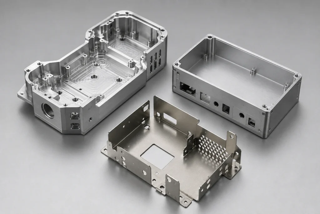
Examples include:
- Angled connector ports
- Compound external surfaces
- Sensor apertures
- Side-access pockets
- Features requiring controlled relationships across several faces
For these geometries, 5-axis CNC machining can improve tool access and reduce unnecessary repositioning.
CNC still should not be treated as the default enclosure process.
| Design Requirement | CNC-Machined Aluminum | Sheet Metal |
|---|---|---|
| Integrated bosses and standoffs | Strong | Usually separate features |
| Deep precision pockets | Strong | Limited |
| Machined gasket grooves | Strong | More difficult |
| Large thin panels | Often inefficient | Strong candidate |
| Complex multi-face ports | Strong | Application-dependent |
| Precision thermal pads | Strong | Limited without added parts |
| Large simple cabinet | Material-intensive | Frequently efficient |
A compact analyzer with integrated standoffs, gasket grooves and thermal interfaces can favor CNC. A large rectangular cabinet with broad thin walls may favor sheet metal.
Hybrid construction can combine both where the design benefits from each process.
Inspection for Medical Device Aluminum Enclosure Machining
Enclosure inspection should follow functional relationships rather than only checking individual dimensions.
A typical plan can include:
- Base and cover flatness
- PCB standoff location
- Connector opening position
- Display or sensor aperture position
- Gasket groove geometry
- Threaded features
- Mating interfaces
- Critical post-finish dimensions
CMM inspection is useful for three-dimensional datum relationships. Vision measurement can support smaller ports and edge geometry, while thread gauges and dedicated fixtures address particular assembly features.
Finishing also changes inspection timing. Critical dimensions affected by anodizing should be identified as post-finish requirements where appropriate.
BOONA guide to machining IVD and analytical instrument components discusses similar relationships among instrument alignment, component geometry, cleanliness and verification.
A dimensional inspection report answers a component-level question: does the enclosure meet the controlled drawing?
Ingress protection, EMC performance, cleaning durability and complete-device safety require separate system-level verification. Keeping those responsibilities distinct prevents the machining supplier’s dimensional documentation from being mistaken for finished-device validation.
Quality-System and Regulatory Boundaries
Medical enclosure procurement also operates within a controlled quality environment.
The FDA’s Quality Management System Regulation became effective on February 2, 2026. The revised 21 CFR Part 820 incorporates ISO 13485:2016 by reference as the foundational medical-device quality-management-system standard.
ISO 14971:2019 provides the international framework for medical-device risk management.
For a machining supplier, relevant customer-controlled requirements can include:
- Drawing and revision control
- Material documentation
- Inspection records
- Surface-finish requirements
- Identification of critical features
- Customer-defined traceability
- Approved manufacturing changes
The medical-device manufacturer retains responsibility for the complete product’s risk management, safety, EMC testing, ingress validation, biological evaluation where applicable, cleaning validation and regulatory release.
This distinction improves both RFQs and supplier communication.
A machining supplier can manufacture an enclosure with a specified gasket groove, grounding land or PCB datum. The functional acceptance criteria for the finished medical device should originate from the product manufacturer’s controlled design and verification process.
Published Application Example: Compact Wearable Optical Electronics
A 2025 peer-reviewed wearable hyperspectral photoplethysmography study provides a useful example of how compact electronics can place several requirements onto a small enclosure.
The researchers packaged their DFSIG-µSPEC microspectrometer in an anodized aluminum case measuring approximately 5.8 × 16 × 24 mm. The optical system covered 550 to 800 nm, achieved an average spectral resolution of 3.4 nm, and produced PPG waveforms across 50 spectral bands.
The subsequently integrated HS-PPG module measured approximately 8 × 16 × 24 mm.
Those dimensions illustrate the packaging problem: miniature optical hardware, electronics and enclosure interfaces occupy only a few centimeters, so sensor alignment and PCB position become tightly connected to the mechanical package.
For a machined enclosure supporting this type of system, relevant considerations could include:
- Optical aperture location
- PCB datum control
- Internal component clearance
- Housing rigidity
- Cable or connector interfaces
- Thermal paths
- Surface finish
This published research example is not a BOONA customer project and does not establish universal machining tolerances. It shows how enclosure geometry becomes part of a compact sensing system’s mechanical architecture.
Common Drawing Mistakes and Supplier Selection
Many enclosure manufacturing problems can be prevented before machining starts.
Common drawing issues include:
- PCB mounting holes referenced from cosmetic walls
- Connector openings controlled from unrelated datums
- Cover flatness left undefined
- Gasket groove requirements without a mating reference
- Anodizing called out without masking details
- Grounding lands coated unintentionally
- Pre-finish and post-finish dimensions mixed together
- Insert installation stage left unclear
- Deep pockets combined with unnecessary sharp internal corners
- Cosmetic areas lacking separate acceptance criteria
- IP ratings placed on a component drawing as though a single housing establishes the rating
- “Medical-grade aluminum” specified without alloy and temper
A useful supplier review asks whether the machining team can identify these conflicts before material is cut.
Buyers should also confirm that critical multi-face relationships can be inspected, surface-finishing requirements can be controlled from the drawing, and required material or dimensional documentation can be supplied.
The RFQ becomes more effective when it identifies which surfaces locate electronics, transfer heat, establish grounding or create the sealing boundary. Those functional details help DFM focus on the features that actually influence the assembled product.
FAQs
What aluminum is commonly used for medical device enclosures?
6061-T6 or T651 is frequently considered for CNC-machined enclosures because it combines useful machinability, structural properties, corrosion resistance and finishing flexibility. Final alloy selection depends on the device’s structural, thermal, environmental and finishing requirements.
Why use CNC machining for an aluminum medical enclosure?
CNC machining is particularly useful where the housing integrates precision pockets, PCB bosses, gasket grooves, thermal surfaces or features located across several faces.
How thin can a CNC aluminum enclosure wall be?
There is no universal safe value. Wall height, overall enclosure size, pocket depth, alloy, stock condition, clamping, machining strategy, flatness and cosmetic requirements all influence practical wall geometry.
Does anodizing affect enclosure dimensions?
Yes. Critical fits, bores, threads, sealing interfaces and electrical contacts should be reviewed according to their final finished condition.
Can anodized aluminum provide EMI shielding?
The aluminum enclosure can form part of an EMC strategy, but the complete result also depends on seams, openings, coatings, grounding, conductive contacts, connectors, cables and electronics.
Does a medical device enclosure need an IP rating?
Only where the product specification requires ingress protection. IEC 60529 defines the IP classification system, while the assembled device configuration must be evaluated against the required protection level.
Conclusion: Design the Enclosure Around the System
Effective medical device aluminum enclosure machining begins with the assembled system rather than an isolated block of aluminum.
Wall stability, PCB position, connector alignment, gasket geometry, thermal interfaces, grounding, anodizing and dimensional inspection all interact. A change made to improve one requirement can affect another, as the anodizing and electrical-contact example demonstrates.
A stronger enclosure drawing identifies functional datums, final-finish dimensions, sealing surfaces, grounding interfaces and inspection conditions before machining begins. It also keeps component-level dimensional verification separate from finished-device EMC, ingress, biological and regulatory validation.
For enclosure development, send BOONA your CAD model, controlled drawing, specified aluminum alloy, surface-finish requirements, critical datums and sealing or grounding interfaces through the CNC machining service for a manufacturability review.


