
A precision equipment team wants to reduce thermal drift in a PEEK positioning component. Replacing unfilled PEEK with carbon-filled material seems straightforward because the reinforced grade is dramatically stiffer. The engineering review, however, reveals another requirement: the same component also provides electrical isolation. Carbon fiber changes that part of the specification by orders of magnitude.
This is the real decision behind PEEK 450G vs CA30 vs GF30. Adding reinforcement changes stiffness, thermal expansion, ductility, density, electrical properties and machining behavior at the same time.
One naming detail matters before comparing the grades. In the Victrex 450 family, the formal grades are 450G, 450CA30 for 30% carbon-fiber reinforcement, and 450GL30 for 30% glass-fiber reinforcement. “GF30” is commonly used as a generic description for 30% glass-filled PEEK, so this guide uses GF30 where discussing the general material category and GL30 when referring to Victrex-specific data.
The right grade depends on what the finished component actually has to do.
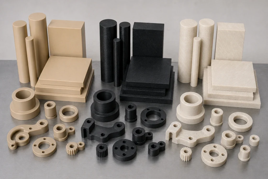
PEEK 450G vs CA30 vs GF30: What Do the Grades Mean?
PEEK 450G is the unreinforced material in this comparison. The current Victrex 450G datasheet describes a semi-crystalline, standard-flow PEEK intended for injection molding and extrusion.
Its 2026 data list a tensile modulus of 4,000 MPa, density of 1.30 g/cm³, and tensile strain at break of 25%.
30% carbon fiber PEEK, represented here by 450CA30, contains carbon reinforcement. The current Victrex 450CA30 data list a tensile modulus of 28,000 MPa and strain at break of only 1.7%. Victrex positions the material for higher stiffness and strength in static or dynamic systems.
30% glass fiber PEEK, represented by 450GL30, sits between the two mechanically. The 450GL30 datasheet gives a tensile modulus of 11,500 MPa and strain at break of 3.0%.
The filler therefore changes far more than the grade name.
PEEK 450G vs CA30 vs GF30 Property Comparison
The current 2026 Victrex data show how different these materials become after reinforcement.
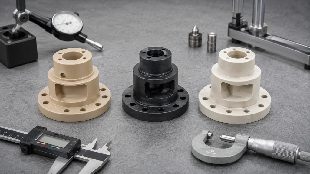
| Property | 450G | 450CA30 | 450GL30 / GF30 |
|---|---|---|---|
| Reinforcement | None | 30% carbon fiber | 30% glass fiber |
| Density | 1.30 g/cm³ | 1.40 g/cm³ | 1.51 g/cm³ |
| Tensile modulus, 23°C | 4.0 GPa | 28 GPa | 11.5 GPa |
| Tensile strain at break | 25% | 1.7% | 3.0% |
| HDT at 1.8 MPa | 152°C | 336°C | 328°C |
| CLTE, flow, below 143°C | 45 ppm/K | 5 ppm/K | 18 ppm/K |
| Volume resistivity, 23°C | 10¹⁶ Ω·cm | 10⁵ Ω·cm | 10¹⁶ Ω·cm |
The modulus comparison is especially striking. At room temperature, 450CA30 has a nominal tensile modulus seven times that of 450G:
28 GPa ÷ 4 GPa = 7
GL30 provides approximately 2.9 times the nominal modulus of 450G.
Tensile strength deserves more careful interpretation. Victrex reports yield stress of 98 MPa for 450G, while CA30 and GL30 are listed with break stress values of 265 MPa and 179 MPa. Because those values describe different failure criteria, a simple three-column “strength ranking” would be misleading.
For preliminary material selection, modulus, CLTE, ductility and electrical properties provide clearer comparisons.
When PEEK 450G Is the Better Choice
Unfilled PEEK should not be treated as a lower-performance version of the reinforced grades.
Its strongest differentiator here is ductility. The current Victrex data give 450G a tensile strain at break of 25%, compared with only 3.0% for GL30 and 1.7% for CA30.
That difference can matter in components containing:
- Thin sections
- Delicate machined edges
- Complex pockets
- Assembly features that see localized strain
- Electrical insulation geometry
- Parts where maximum stiffness is unnecessary
450G also maintains a listed volume resistivity of 10¹⁶ Ω·cm at 23°C, making electrical isolation one of its useful characteristics.
Its lower density can also matter where moving mass or component weight is controlled.
A practical PEEK grade selection process should therefore ask whether adding reinforcement solves an actual engineering problem. If the unfilled grade already satisfies deflection, thermal movement and mechanical requirements, a filler may add abrasiveness, anisotropy and reduced ductility without providing a necessary functional benefit.
BOONA guide to PEEK CNC machining for high-precision custom parts provides additional context for stock condition, stress control and precision PEEK geometry.
When CA30 Carbon-Filled PEEK Makes Sense
CA30 becomes a strong candidate when stiffness and dimensional response under temperature dominate the design.
Its nominal 28 GPa tensile modulus is about seven times the 4 GPa value listed for 450G. The difference in thermal expansion is similarly significant.
Below 143°C in the flow direction, Victrex lists:
- 450G: 45 ppm/K
- 450CA30: 5 ppm/K
That is roughly a ninefold difference in nominal CLTE.
Potential applications include structural guides, high-temperature supports, positioning components, wear-related parts and fixtures where thermal drift must be controlled.
Carbon reinforcement also comes with a major electrical trade-off.
The current CA30 datasheet lists volume resistivity at approximately 10⁵ Ω·cm, compared with 10¹⁶ Ω·cm for 450G.
That difference can remove CA30 from consideration before mechanical stiffness becomes the deciding factor.
The low 1.7% strain at break also means delicate geometry deserves review. A design created around the more ductile 450G grade should not automatically move to CA30 without reconsidering small edges, interference features and local strain.
When GF30 or 450GL30 Is the Better Compromise
The most useful way to understand carbon filled PEEK vs glass filled PEEK is to stop viewing GL30 as a reduced-performance CA30.
The materials solve different combinations of requirements.
450GL30 increases tensile modulus from 4 GPa for 450G to 11.5 GPa, while reducing nominal flow-direction CLTE from 45 to 18 ppm/K.
At the same time, GL30 retains a listed volume resistivity of approximately 10¹⁶ Ω·cm at 23°C. That is the same order of magnitude as unfilled 450G and dramatically different from carbon-filled CA30.
That combination makes GL30 worth evaluating for:
- High-temperature electrical supports
- Semiconductor equipment fixtures
- Sensor carriers
- Precision insulating spacers
- Structural electrical components
- Parts requiring more stiffness than unfilled PEEK
There are still trade-offs. GL30’s strain at break is only 3%, and its density of 1.51 g/cm³ is the highest of these three grades.
For an electrically isolated structure, however, its balance of reinforcement and resistivity may be more useful than CA30’s maximum modulus.
Thermal Expansion Can Change the Whole Material Decision
CLTE numbers become easier to understand when translated into a simple engineering example.
Consider a semiconductor alignment fixture with a 100 mm reference distance. Assume, only for comparison, that the relevant material direction follows the datasheet flow direction and that the part experiences a 100°C temperature rise while remaining below 143°C.
Using the nominal Victrex CLTE data:
- 450G: 100 mm × 45 ppm/K × 100 K ≈ 0.45 mm
- 450GL30: 100 mm × 18 ppm/K × 100 K ≈ 0.18 mm
- 450CA30: 100 mm × 5 ppm/K × 100 K ≈ 0.05 mm
The nominal difference between 450G and CA30 is therefore about 0.40 mm over that 100 mm reference length in this simplified calculation. The underlying CLTE values come directly from the 2026 datasheets.
This is an illustrative engineering calculation, not a guaranteed prediction for a finished machined fixture.
Actual movement depends on stock form, orientation, constraints, geometry, machining stress and the real temperature distribution.
Now add an electrical-insulation requirement. CA30’s low expansion may look ideal, but its electrical resistivity may eliminate it. GL30 can then become the more balanced candidate.
Fiber Reinforcement Changes PEEK Machining Behavior
Material replacement also changes reinforced PEEK machining.
Unfilled 450G is comparatively ductile. Machining concerns often involve burr formation, heat, clamping pressure, stress release and maintaining delicate features without deformation.
Carbon and glass fibers introduce abrasive reinforcement. Tool edge condition becomes more important, especially around small holes, sharp exits and precision surfaces.
A 2025 peer-reviewed CF/PEEK machining study investigated cutting force, cutting temperature, surface roughness and fiber-fracture modes under different machining conditions and fiber orientations. The study reinforces the practical point that machining behavior changes with fiber orientation and cutting strategy.
Machining planning for CA30 and GF30 should consider:
- Tool wear
- Fiber breakout
- Entry and exit edges
- Bore quality
- Edge chipping
- Surface condition
- Thin-wall support
- Fiber orientation
These considerations do not justify inventing one universal spindle speed, feed rate or tool-life figure.
The appropriate process depends on the stock, geometry, machine, cutter and required finish.
Datasheet Values Are Material Comparison Data
A grade name does not completely define the condition of a machined PEEK blank.
Victrex explicitly states that its current property data should be used for material comparison and that actual values can depend on part geometry, processing conditions and direction.
That warning is particularly relevant to reinforced grades.
The current molding data illustrate directional behavior:
450CA30 molding shrinkage
- Flow: 0.10%
- Across flow: 0.50%
450GL30 molding shrinkage
- Flow: 0.30%
- Across flow: 0.90%
Those values are molding data. They should not be copied into a CNC drawing as predicted shrinkage for machined stock.
They do demonstrate why orientation matters in fiber-reinforced materials.
A precision-machining RFQ should therefore specify more than simply “PEEK CA30” or “PEEK GF30.” Useful information includes exact grade, stock form, certification requirements, filler content, required traceability, critical orientation if applicable and operating conditions.
That becomes especially valuable where the component has tight hole patterns, flatness requirements or temperature-sensitive positioning features.
Wear Applications Need More Than a Modulus Comparison
Wear components provide a useful real-world reminder that material selection depends on the complete contact system.
A 2024 peer-reviewed study on PEEK composites under oil lubrication investigated modified PEEK for self-lubricating components relevant to low-speed, heavy-load hydraulic motor conditions. The paper also summarizes prior research on 30% carbon-fiber PEEK.
In those cited 30% CF tests, friction coefficients ranged from approximately 0.03 to 0.07, representing a reported 25% to 33% reduction relative to unmodified PEEK under the specific experimental conditions.
Those numbers are not universal CA30 bearing specifications.
Counterface material, lubrication, load, speed, fiber formulation and surface condition can all change tribological behavior.
The same principle applies to glass-filled material. A high modulus does not automatically mean low wear, and a lower coefficient of friction in one laboratory configuration does not guarantee superior life in another assembly.
For a machined bearing, guide or sliding ring, the design review should consider the two mating materials, lubrication condition, temperature, pressure, speed and allowable wear together.
DFM for PEEK 450G vs CA30 vs GF30 Machined Parts
Changing filler should trigger a new DFM review.
A drawing developed around 450G may contain thin sections or small edges that rely on its greater ductility. CA30 and GL30 provide more stiffness but much lower elongation.
Features worth reviewing include:
- Thin walls
- Fine threads
- Press fits
- Small drilled holes
- Sharp corners
- Deep pockets
- Narrow slots
- Bearing surfaces
- Tight flatness
- Unsupported edges
💡 Pro Tip: Treat a switch from 450G to CA30 or GF30 as an engineering material revision. Recheck critical fits, edge conditions, thermal movement and inspection methods before releasing the new material.
Fiber orientation also deserves discussion where the stock supplier can provide direction information. A long precision feature aligned differently within reinforced stock may respond differently to machining or temperature.
For difficult geometries, BOONA precision machining service can support drawing and tolerance review before expensive high-performance plastic stock is cut.
PEEK Grade Selection Matrix
No grade wins every requirement.
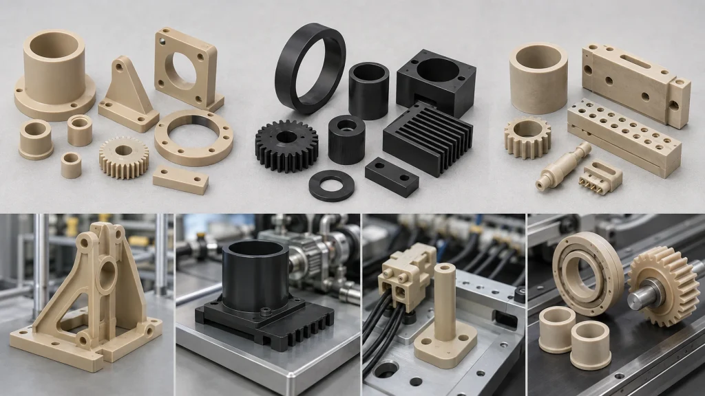
| Requirement | 450G | 450CA30 | 450GL30 / GF30 |
|---|---|---|---|
| Ductility | Highest of three | Lowest | Intermediate |
| Structural stiffness | Lowest | Highest | Higher than 450G |
| Low flow-direction CLTE | Moderate | Strongest | Strong |
| Electrical insulation | Strong | Requires review | Strong |
| Low density | Lowest density | Intermediate | Highest density |
| Fine delicate geometry | Strong candidate | Review carefully | Review carefully |
| Wear application | Application-dependent | Strong candidate | Application-dependent |
| Insulating structure | Strong | Often less suitable | Strong candidate |
| High-temperature structural part | Application-dependent | Strong candidate | Strong candidate |
A semiconductor fixture with electrical isolation may lead toward GL30.
A thermally stable mechanical guide may lead toward CA30.
A complicated insulator with delicate edges may remain better suited to 450G.
The design should start with the requirement and work backward to the material.
FAQs
What is the difference between PEEK 450G and CA30?
450G is unfilled PEEK. 450CA30 contains 30% carbon fiber. CA30 has much higher stiffness and lower nominal flow-direction thermal expansion, while 450G has substantially greater elongation and much higher electrical resistivity.
What does GF30 mean in PEEK?
GF30 generally describes PEEK containing 30% glass fiber. In the Victrex 450 family, the formal grade discussed here is 450GL30.
Is carbon-filled PEEK stronger than glass-filled PEEK?
450CA30 has a higher tensile modulus than 450GL30 in the current Victrex data. “Stronger” alone is too broad for material selection because ductility, thermal expansion, electrical behavior, wear and actual load conditions also matter.
Is glass-filled PEEK electrically insulating?
Victrex currently lists 450GL30 volume resistivity at approximately 10¹⁶ Ω·cm at 23°C. The corresponding value for 450CA30 is approximately 10⁵ Ω·cm.
Which PEEK grade has the lowest thermal expansion?
Among these three grades, 450CA30 has the lowest listed flow-direction CLTE below 143°C at 5 ppm/K. Finished-part dimensional change still depends on geometry, orientation and constraint.
Can I replace 450G with CA30 or GF30 without changing the drawing?
The substitution should receive an engineering review. Reinforcement changes stiffness, elongation, thermal response, density, electrical behavior and machining characteristics.
Conclusion: Choose the Filler Around the Function
The practical answer to PEEK 450G vs CA30 vs GF30 depends on the component’s functional requirements.
450G offers the highest ductility of the three and strong electrical insulation. CA30 delivers the highest stiffness and lowest nominal flow-direction thermal expansion, while its electrical properties require careful review. GF30 or 450GL30 provides a useful middle ground with reinforced stiffness and strong electrical insulation.
Operating load, temperature range, allowable thermal drift, electrical isolation, wear conditions, mating materials, geometry and stock orientation should all enter the selection.
The RFQ should also specify the exact grade rather than simply stating “PEEK.”
Send BOONA your CAD file, critical dimensions, operating conditions and required grade through the PEEK CNC machining service for a DFM and manufacturability review before cutting expensive reinforced PEEK stock.


