
A premium headphone prototype can sound right and still fail its mechanical review. One earcup rotates more freely than the other. The driver fits, yet its mounting ring sits slightly off-center. Two anodized cups show different reflections under the same light, while a folding hinge begins to bind after the fasteners are tightened.
These are the kinds of problems that make machining parts for audio equipment more than a matter of cutting metal to CAD dimensions.
Headphones, DACs, amplifiers and audio interfaces combine acoustic components with precision mechanisms, user controls and highly visible surfaces. Their machined parts influence driver position, assembly fit, hinge motion, product weight and perceived quality.
A useful prototype therefore needs to reproduce the mechanical relationships that the finished audio system actually depends on.
What Parts Are Commonly Machined for Audio Equipment?
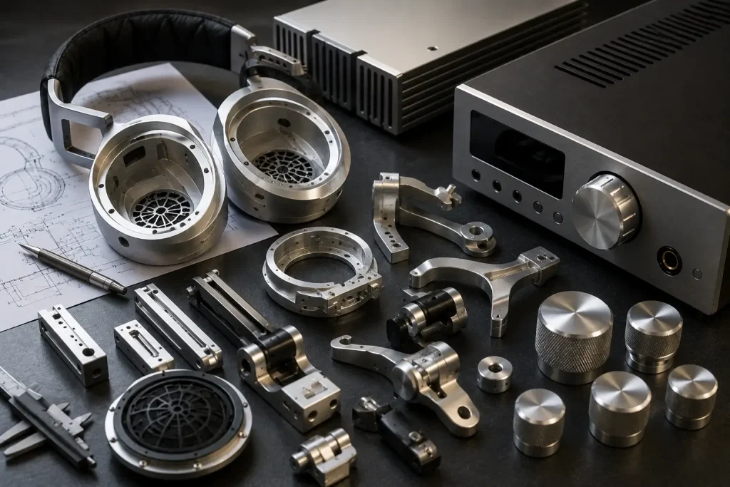
Headphone parts machining covers structural, adjustment and cosmetic components rather than only the outer earcup.
Typical parts include:
- Aluminum earcups
- Driver mounting rings
- Yokes and forks
- Pivot blocks
- Folding hinges
- Headband sliders
- Cable-entry components
- Connector housings
- Adjustment mechanisms
- Decorative trim
Audio electronics create another group of machining requirements:
- DAC housings
- Headphone amplifier chassis
- Audio-interface enclosures
- Front and rear panels
- Volume and encoder knobs
- Display bezels
- Connector plates
- Internal brackets
- Heat-spreading chassis parts
Audio equipment CNC machining becomes particularly useful when several functional features need to stay accurately related.
Consider a desktop DAC front panel. Its display, volume encoder, headphone jack and buttons may each meet their individual dimensional tolerance while still looking misaligned after assembly if they were referenced from unrelated datums.
Headphones create the same problem with paired components. A yoke, pivot and earcup can each pass inspection while the completed joint still shows excess play or uneven rotation.
For that reason, DFM should start from the complete assembly rather than treating every component as an isolated CNC part.
Why Headphone Components Are Mechanically Demanding
CNC headphone parts often combine low weight, curved geometry, moving interfaces and Class-A cosmetic surfaces.
An earcup may contain a deep internal cavity while its exterior remains thin and visually smooth. The yoke has to support the cup and permit controlled rotation. A slider must move repeatedly without obvious looseness, while both sides of the headphone should feel similar.
Ergonomic geometry adds another requirement.
A 2024 peer-reviewed Springer study on over-ear headphone force comfort collected 3D head and ear measurements from 30 subjects with balanced gender representation and measured four different headphones. The researchers found that earmuff size alone did not determine wearing comfort, while force comfort showed a positive relationship with overall perceived comfort.
That finding is relevant to mechanical development because the forces experienced by a wearer emerge from the complete headband, yoke, slider and earcup system.
The machining supplier does not define the desired clamping force, but prototype components must reproduce the geometry closely enough for the product team to evaluate it.
Paired appearance deserves similar attention. Slight differences in tool marks, bead blasting or anodized tone become easier to notice when the left and right components sit beside each other.
Machining Parts for Audio Equipment: Earcups and Enclosures
Headphone enclosure machining combines deep pocket removal with a demanding cosmetic exterior.
A machined earcup can incorporate:
- Driver seating diameter
- Internal acoustic cavity
- Baffle interfaces
- Vent openings
- Cable passages
- Pad-retaining geometry
- Threaded bosses
- Yoke mounting features
- Decorative contours
As material is removed from an aluminum billet, the remaining shell becomes less rigid. Cutter force, fixture pressure and residual stress can then influence wall shape.
Potential machining risks include:
- Thin-wall vibration
- Chatter
- Local deflection
- Base or rim distortion
- Visible setup transitions
- Poor access to deep internal corners
Curved earcups also tend to distribute features around several faces. For suitable geometry, 5-axis CNC machining can improve access to contours, vents and pivot interfaces while reducing unnecessary repositioning.
The engineering benefit is setup and tool-access control rather than an automatic guarantee of tighter tolerances.
Weight reduction should also be selective. Removing material from broad low-load areas can make sense, while hinge mounts, threaded bosses and pad interfaces may need more local stiffness.
Uniform wall transitions and realistic internal radii usually produce a more stable machining strategy than aggressively thinning every section.
Yokes, Hinges and Headband Adjustment Mechanisms
Headphone mechanisms are judged by movement as much as by dimensional inspection.
A premium design may use:
- Fork-style yokes
- Single-arm pivots
- Rotating earcup joints
- Folding hinges
- Slider rails
- Detent mechanisms
- Pivot screws
- Bushings or inserts
Important relationships include bore position, coaxiality, parallelism, axial clearance and the location of mating faces.
A hinge with too much clearance can feel loose. Too little clearance can cause binding, particularly after surface finishing changes a critical interface.
Designers should therefore define the desired assembled condition before reducing individual tolerances.
💡 Pro Tip: Specify the functional pivot relationship first. A very tight bore tolerance cannot compensate for two pivot holes whose axes are poorly related to each other.
Cable routing deserves attention during the same review. Folding and rotating headphones often route a wire through or beside the moving joint. A mechanism can perform perfectly in a bare-metal assembly and still damage the cable once the electrical components are installed.
Wear is another reason to evaluate materials by feature. Aluminum can reduce overall mass, while harder pins, inserts or bushings may be appropriate at selected high-contact interfaces.
The final choice depends on load, movement cycle, finish and product architecture rather than a universal headphone material rule.
How Machined Geometry Interacts With Headphone Acoustics
Machining controls several physical boundaries that the acoustic team may depend on.
These can include:
- Driver position
- Driver mounting diameter
- Baffle geometry
- Internal cavity volume
- Vent diameter
- Port position
- Damping-material supports
- Pad seating geometry
- Enclosure stiffness
The current IEC 60268-7:2025 applies to headphones, earphones, headsets and earsets and specifies characteristics and relevant methods of measurement for headphone systems. The 2025 publication is the fourth edition and replaced the previous 2010 edition plus its 2020 amendment.
That system-level perspective is useful during DFM.
A pocket that appears to be removable excess material may form part of the acoustic cavity. Moving a hole to simplify tool access can alter an intended vent path. Thickening a wall around a hinge can consume internal volume that the acoustic model assumed was available.
CNC machining does not create good sound by itself.
Its role is to reproduce the mechanical geometry consistently so the acoustic team can evaluate the intended driver, cavity, damping, pads, vents and electronics instead of testing an accidental variation of the design.
Acoustically controlled features should therefore be identified before machining simplifications are approved.
Published Example: Open-Back Headphone Sound Leakage
A 2025 research project provides a useful example of enclosure geometry affecting an acoustic objective without changing the basic idea of an open-back headphone.
Researchers investigated an enclosure designed to reduce outward sound leakage. The published IEEE study on an open-back headphone enclosure reported an average 7.6 dB reduction in normalized sound leakage between 1,000 and 7,000 Hz compared with the reference configuration.
The engineering issue in this case was leakage through enclosure architecture rather than mechanical breakage.
That makes the study useful for prototype machining.
Openings, vent structures and the geometry surrounding an open-back driver may look like ordinary cosmetic or weight-reduction features to someone reviewing the part only for manufacturability. Changing them without understanding their purpose can change the test result.
A controlled CNC prototype can support this type of development because revised enclosure geometries can be manufactured while preserving key references such as driver location, mounting interfaces and overall assembly position.
The 7.6 dB value belongs only to the researchers’ specific design and test configuration. It should not be reused as a general performance claim for CNC-machined headphones or BOONA projects.
The broader lesson is that enclosure features should be classified by function before a machinist simplifies them.
Machining Parts for Audio Equipment: DACs, Amplifiers and Controls
Amplifier enclosure machining shifts the focus from wearable mechanisms to control alignment, connector support and enclosure appearance.
A machined DAC or amplifier chassis may integrate:
- PCB bosses
- Front display openings
- Rotary encoder holes
- Headphone sockets
- XLR and RCA openings
- USB and power connectors
- Ventilation
- Internal partitions
- Heat-spreading surfaces
- Feet and mounting points
Front panels create particularly visible tolerance stacks.
Consider this relationship:
PCB → encoder → front panel → knob
If the PCB mounting holes, encoder shaft opening and visible front-panel geometry reference different datums, the volume knob can appear off-center even though every individual dimension passes inspection.
Rear connector panels behave similarly. A connector opening should be positioned around the hardware it serves, rather than simply dimensioned from an unrelated cosmetic edge.
Control components require their own DFM.
Volume and selector knobs may use round bores, D-flats, set screws, knurling, indicator grooves and decorative chamfers. Bore concentricity affects visible wobble, while axial position determines whether the knob sits consistently relative to the panel.
A heavier brass or stainless control can create a different tactile response from aluminum, but knob mass should be treated as an interface choice rather than an acoustic-performance claim.
Choosing Materials and Reducing Weight
Material selection should follow structure, weight, wear and finishing requirements.
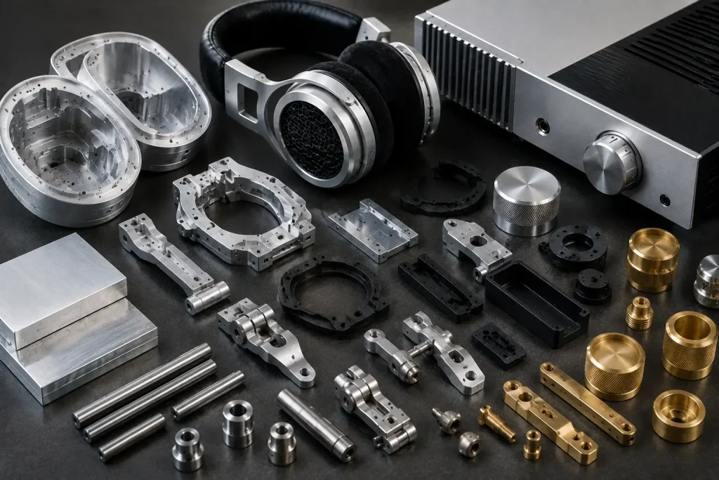
| Material | Useful Characteristics | Typical Applications |
|---|---|---|
| 6061 aluminum | Low density, machinable, anodizable | Earcups, chassis, knobs, yokes |
| 7075 aluminum | Higher strength than common 6061 tempers | Thin structural yokes, loaded parts |
| Stainless steel | Wear resistance and stiffness | Pins, sliders, hinges, trim |
| Brass | Higher density and decorative appearance | Knobs, inserts, accents |
| Engineering plastic | Low mass and electrical isolation | Internal guides, covers, mounts |
6061 is often a practical candidate for machined cosmetic audio parts because it supports extensive machining and common surface finishes.
For deeply pocketed parts, stock condition also matters. BOONA guide to 6061-T6 vs 6061-T651 explains why the stress-relieved T651 condition can provide a more predictable starting point for plates or parts involving large asymmetric material removal.
7075 deserves consideration where the actual structural load needs additional strength, particularly around thin mechanisms. It should not be selected simply because its strength number is higher.
Headphone weight reduction works best when material is removed selectively. Large cavities and low-load walls offer different opportunities from hinge interfaces or threaded fastener regions.
The finished mass target belongs to the product team; machining DFM should preserve the structural features required to achieve it reliably.
Surface Finish, Cosmetic Matching and Inspection
Audio hardware is often viewed from close range, making machining and finishing defects easy to see.
Common options include:
- Bead blasting
- Clear anodizing
- Black anodizing
- Colored anodizing
- Brushing
- Polishing
- Laser marking
- Knurling
Deep tool transitions, chatter or fixture marks can remain visible after finishing. Blasting can soften fine machining patterns, but it cannot reliably hide every defect.
Left and right headphone components should be reviewed together where color and surface matching matter. The same principle applies to an amplifier chassis and its removable front panel.
BOONA surface finishing options provide useful context for selecting post-machining treatments while the design is still under review.
Dimensional and cosmetic inspection should remain separate activities.
Functional checks may include:
- Driver-seat diameter
- Pivot-hole location
- Hinge alignment
- Slider fit
- Knob-bore concentricity
- Front-panel opening position
- Connector alignment
- Thread condition
Cosmetic inspection addresses scratches, dents, tool marks, blasting uniformity and finish consistency.
Drawings should also identify whether critical dimensions apply before or after finishing. A coating-sensitive joint should not rely on an unstated assumption about which condition the inspector measures.
From Appearance Model to Functional Audio Prototype
A staged development process keeps early design questions from becoming expensive metal revisions.
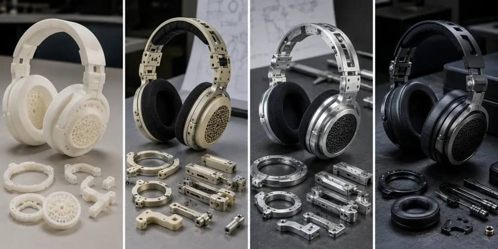
Stage 1: Form and Ergonomics
Evaluate head fit, earcup size, control position, product proportions and industrial design. Fast additive prototypes may be sufficient at this stage.
Stage 2: Mechanical Assembly
Introduce representative drivers, PCBs, hinges, sliders, connectors and cable routing. This exposes interference and tolerance-stack problems.
Stage 3: CNC Functional Prototype
Production-like metals become useful when the team needs to evaluate real threads, hinge stiffness, thin-wall behavior, control alignment and finishing.
Stage 4: Pre-Production Assembly
The build should increasingly match the intended materials, surface treatments and assembly architecture so acoustic and electrical testing occurs in representative mechanical hardware.
A useful audio RFQ should include more than standalone part files.
Provide:
- Complete 3D assembly
- Controlled 2D drawings
- Driver or PCB reference geometry
- Critical datums
- Hinge and slider interfaces
- Cable-routing requirements
- Material
- Finish
- Cosmetic surfaces
- Left/right matching requirements
- Critical post-finish dimensions
The additional assembly context lets manufacturing engineers distinguish acoustic, structural and cosmetic features from ordinary clearance geometry.
FAQs
What headphone parts can be CNC machined?
Earcups, yokes, pivot blocks, hinges, sliders, driver rings, connector housings and decorative trim can all be machined when their geometry and material suit CNC manufacturing.
Is aluminum suitable for headphone earcups?
Yes. Aluminum offers relatively low mass, useful stiffness, machinability and several finishing options. Final acoustic performance still depends on the complete driver, enclosure, vents, damping and ear-pad system.
Can CNC machining improve headphone sound quality?
CNC can accurately reproduce driver location, cavity geometry, baffles and vents that the acoustic design depends on. Sound quality remains a system-level result rather than a property of the machining process alone.
Why use CNC machining for premium audio equipment?
CNC supports integrated bosses, multi-face connector openings, rigid metal panels, precision mechanisms and production-representative prototypes without requiring dedicated casting tooling.
What material is best for audio volume knobs?
Aluminum, stainless steel and brass are all possible choices. Selection depends on desired mass, appearance, surface finish, wear and tactile response.
What should be included in an audio machining RFQ?
Send the current CAD assembly, controlled drawings, material, finish and critical interfaces. For headphones, include driver, hinge and cable references. For DACs and amplifiers, include PCB, display, connector and control geometry.
Conclusion: Machine the Part Around the Complete Audio System
Successful machining parts for audio equipment starts with understanding what each feature does in the complete assembly.
An earcup relates to its driver, vents, pad and yoke. A hinge relates to both the adjustment mechanism and internal cable path. A DAC front panel depends on the PCB, encoder, display, connectors and control knobs.
Material choice, machining sequence, tolerance strategy and surface finish should follow those relationships.
Early models can validate ergonomics and appearance. Mechanical builds can expose packaging and hinge problems. Later CNC prototypes can test production-like metal geometry, assembly alignment and cosmetic finish before the design is frozen.
For headphones, DACs, amplifiers, audio interfaces or other precision audio hardware, send the assembly CAD, controlled drawings, material, finish and critical interfaces through BOONA CNC machining service for a manufacturability review. Send your CAD for a DFM review.


