
An RFQ for sheet metal enclosures specifies 1.5 mm cold-rolled steel, black powder coating, a fan cutout, and an IP54 target. Yet the package says nothing about internal heat loads, masked grounding zones, gasket compression, cable clearance, or whether door flatness applies free or latched. Each omission can force changes across the flat pattern, hardware, wiring, finish, and verification plan.
Successful enclosures coordinate structure, airflow, cable access, sealing, electrical bonding, assembly, and maintenance before production. The following design decisions turn cut and bent panels into dependable electronics housings.
What Are Sheet Metal Enclosures and Cabinets?
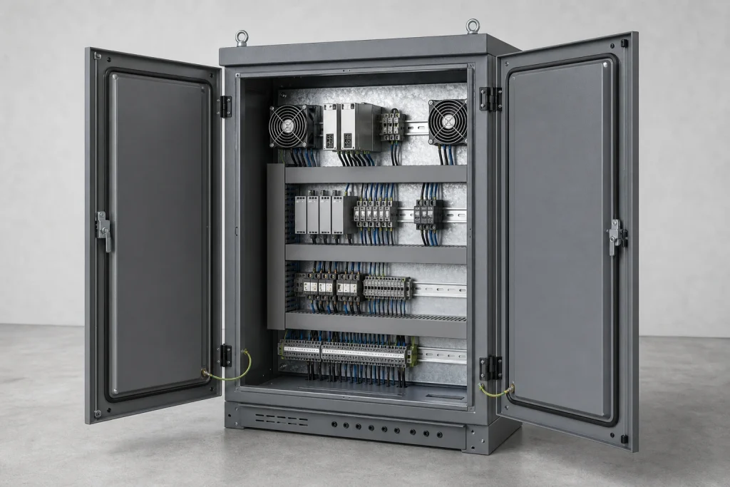
Sheet metal enclosures range from palm-sized instrument boxes to wall-mounted control panels and floor-standing equipment cabinets. A compact chassis may locate a PCB, display, and connectors. A larger cabinet can carry power distribution, drives, relays, network switches, fans, filters, and removable mounting plates.
“Enclosure,” “cabinet,” “chassis,” and “rack” overlap in industry usage. Construction may use one folded shell, assembled panels, a welded frame, or a hybrid structure. The drawing and bill of materials should therefore define the assembly, internal mounting, service access, and standardized interfaces.
Common applications include machine controls, telecommunications hardware, laboratory instruments, battery-management systems, power converters, edge computers, and outdoor monitoring equipment. Across these products, the housing influences far more than appearance. Panel stiffness affects connector alignment, seams affect shielding, vent geometry affects cooling, and door flatness affects gasket compression.
Material Choices for Sheet Metal Enclosures
Material selection should follow the service environment, forming geometry, weight target, finish, grounding strategy, and cost structure.
Aluminum
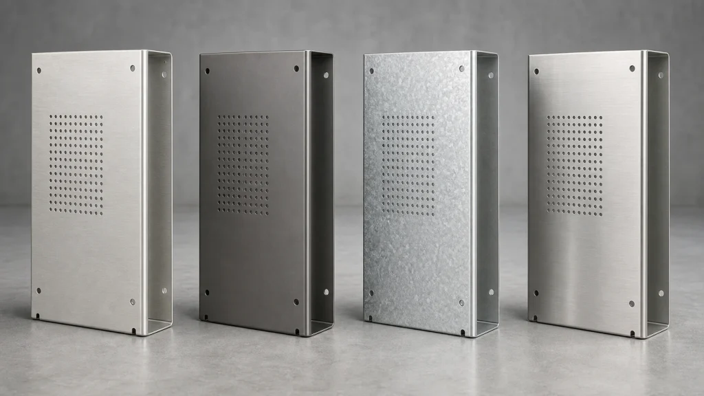
Aluminum reduces mass, resists corrosion, and conducts heat well. 5052-H32 is a common candidate for covers, pans, and multi-bend housings because it forms more reliably than precipitation-hardened 6061-T6. Aluminum is less stiff than steel at equal thickness, so broad panels may need returns, beads, ribs, or added section depth.
Cold-Rolled and Galvanized Steel
Cold-rolled steel provides high stiffness, predictable forming, weldability, and an economical base for powder coating. It suits indoor control cabinets and equipment chassis where weight is secondary. Galvanized or electro-galvanized sheet adds corrosion protection, although cut edges, weld zones, grounding points, and finish compatibility require attention.
Stainless Steel
304 and 316 stainless steel serve washdown, laboratory, marine, and outdoor applications. Their corrosion resistance and cleanability come with higher cost, forming force, and mass.
| Material | Main advantage | Primary design concern | Typical enclosure role |
|---|---|---|---|
| 5052-H32 aluminum | Low mass and good formability | Lower panel stiffness than steel | Covers, boxes, instrument housings |
| Cold-rolled steel | Stiff and economical | Requires corrosion-protective finish | Indoor control cabinets |
| Galvanized steel | Built-in corrosion protection | Cut edges and weld areas | Utility and HVAC controls |
| 304/316 stainless steel | Corrosion resistance and cleanability | Forming load, weight, and cost | Washdown or outdoor cabinets |
Sheet Metal Enclosure Design Priorities
Thickness alone does not create a rigid cabinet. A shallow flat door can oil-can or twist even when the material seems heavy, while a thinner panel with hems, return flanges, and formed ribs can remain stable. Start with load paths: wall mounting, hinge reactions, cable pull, transformer weight, handle loads, and vibration all enter the structure differently.
Bend design comes next. Inside radius, material thickness, temper, grain direction, tooling, and bend angle influence cracking and springback. Holes or louvers placed too close to a bend can distort, and short flanges may leave insufficient support for press-brake tooling. Use the fabricator’s qualified bend data rather than a universal K-factor copied across every alloy and thickness.
Datum strategy keeps assemblies aligned. PCB standoffs, connector cutouts, hinge axes, latch positions, and gasket lands should reference functional surfaces. Overly tight tolerances on every hole raise inspection and production effort without improving the finished product. Reserve stronger controls for interfaces that locate electronics, close a seal, or mate with another assembly.
Pro Tip: Release both the formed-part model and the controlled drawing. The model communicates geometry, while the drawing defines material, grain-sensitive bends, datums, finish, masking, hardware, and inspection condition.
Cutting, Bending, Joining, and Precision Features
Laser cutting handles varied profiles, slots, fan openings, and connector cutouts without dedicated blanking tools. CNC punching becomes attractive for repeated holes, louvers, knockouts, and formed features when the geometry and quantity suit available tooling. Small webs between dense perforations need review because cutting heat and residual stress can distort a broad panel.
Press-brake sequencing determines whether later bends remain accessible. Deep returns, opposing flanges, and internal hems can collide with the punch, die, or completed geometry. A manufacturable flat pattern accounts for bend deduction, reliefs, tool access, and the order in which features form.
Assembly options include spot welding, TIG or MIG welding, rivets, screws, tabs and slots, clinch nuts, and self-clinching studs. Welding produces rigid structures but introduces heat distortion and finishing work. Mechanical fastening supports service and panel replacement while adding hardware and tolerance interfaces.
Some cabinets also need machined heat-spreader blocks, precision connector plates, or rigid mounting rails. A hybrid design can combine formed panels with CNC-machined functional components where flatness, threads, or multi-face relationships exceed practical sheet-metal control.
Hardware, Doors, and Service Access
Hardware decisions affect both fabrication and field service. Self-clinching fasteners need suitable sheet thickness, hole preparation, edge distance, installation direction, and access. Placing a nut beside a bend or behind a welded partition can make installation impossible. Purchased hinges, latches, handles, glands, and filters should appear in the assembly model with their real operating envelopes.
Door behavior deserves separate review. The hinge carries door mass and any equipment mounted to it, while the latch must draw the perimeter into controlled gasket compression. Long doors may need multiple latching points or structural returns. Coating buildup around hinges and tight slots can also change fit.
Inside the cabinet, DIN rails, cable ducts, grounding bars, fan guards, removable trays, and mounting plates compete for space. Leave realistic screwdriver, wrench, cable-bend, and connector-mating clearance. A layout that fits in CAD may still force technicians to remove unrelated components during installation. Good service access reduces assembly time and makes later maintenance less error-prone.
Thermal Management in Electronics Cabinets
Thermal design begins with internal power loss, ambient range, component limits, enclosure orientation, and contamination risk. Passive arrangements use panel conduction, natural convection, louvers, and external surface area. Active systems add fans, filters, ducts, or air-to-air heat exchangers. Sealed cabinets may require a conductive path or closed-loop cooling because exchanging air also admits dust and moisture.
Component spacing and placement can matter as much as fan capacity. A 2025 peer-reviewed study of high-speed train electrical cabinets modeled installation gaps from 0 to 10 mm. Moving a high-loss component group into a higher-flow position reduced the reported maximum temperature from 178°C to 109°C, a 39% decrease under that study’s defined extreme condition. The result demonstrates sensitivity to layout; it is not a general cabinet temperature prediction.
Cooling hardware also needs evidence. A 2022 experimental electrical-cabinet study reported keeping the enclosure temperature below 60°C at a 2,000 W heat load in its test configuration. That scale shows why thermal strategy must come from the actual heat load rather than enclosure size alone. Validate the final arrangement with representative components, wiring, filters, and ambient conditions.
EMI, Grounding, and Environmental Protection
A conductive cabinet can support electromagnetic compatibility only when current has a controlled path across seams, doors, covers, and connector shells. Paint and powder coat interrupt metal-to-metal contact. Drawings should therefore identify masked bonding pads, grounding studs, conductive gaskets, finger stock, and hardware that maintains contact through the expected service life.
Apertures deserve attention because vents, displays, cable entries, and poorly bonded seams can weaken shielding. IEC 61000-5-7 describes methods for evaluating empty-enclosure shielding from 10 kHz to 40 GHz. Empty-cabinet performance still does not establish compliance for populated equipment; PCB layout, filters, cables, connectors, and grounding architecture remain part of system testing.
Ingress protection creates another chain of interfaces. The IEC 60529 IP Code classifies protection provided by electrical enclosures against access, solid foreign objects, and water. Gasket cross-section, compression, corner continuity, door flatness, screw spacing, glands, vents, and drain paths all influence the final result. Treat the requested IP rating as a complete-assembly validation target. A fabricated panel alone cannot carry the certification of the finished cabinet.
Surface Finishes and Functional Masking
Finish selection affects corrosion, appearance, wear, electrical bonding, and dimensional fit. Powder coating works well on steel and aluminum cabinets, with colors and textures suited to industrial equipment. Coating thickness must be considered around hinges, inserted hardware, close-fitting tabs, and mating slots. Threads, gasket lands, and grounding zones may need masking.
Anodizing suits aluminum chassis and panels where corrosion resistance and a durable appearance matter. Because the anodic layer is electrically insulating relative to bare aluminum, the drawing should identify every conductive contact area. Stainless steel may use passivation or a brushed finish, with grain direction controlled across visible panels.
Cosmetic requirements also need boundaries. Define primary appearance surfaces, permissible weld read-through, grinding expectations, gloss, texture, and color standard. A finish sample can settle expectations before a larger run. BOONA surface finishing options provide a useful starting point, while the project drawing should still specify the exact process and protected interfaces.
Mini Case: Thermal Layout in a Rail Electrical Cabinet
The 2025 high-speed electric multiple-unit study offers a useful real-world cabinet example. Researchers examined a traction electrical cabinet in which several component temperature rises exceeded a 60°C limit under the modeled full-power condition. Rather than selecting a larger enclosure or changing the cabinet material, they investigated spacing, component position, airflow, and inlet shape.
Their final configuration used a 4 mm installation gap for the high-loss breakers, moved those components to a region with stronger airflow, changed the inlet to a 2:1 rectangle, and set extreme-condition airflow at 10 m³/min. In the model, that combination brought component temperature rise to the specified 60°C limit.
This is a published rail-industry study, not a BOONA customer project, and its values should not be transferred directly to another cabinet. Its manufacturing lesson is widely useful: the panel cutouts, rail positions, mounting-hole pattern, and airflow path encode thermal decisions. Once production drawings freeze those features, correcting a layout problem can require new panels, wiring changes, and revalidation. Thermal review should therefore occur before release of the flat pattern.
Quality Control and RFQ Requirements
Inspection should follow enclosure function. Typical checks include material and thickness verification, flat-pattern features, bend angles, flange positions, door fit, mounting-hole relationships, inserted-hardware security, weld condition, and coating quality. Functional fixtures can verify connector fit, hinge motion, latch engagement, or mating-panel alignment more efficiently than isolated coordinate measurements.
State the inspection condition. A large panel can assume a different shape when free, clamped to a frame, or fully assembled. Flatness and hole position requirements need to identify which state governs acceptance. Finish inspection should cover coating thickness, adhesion, color, texture, masking, and exposed edges where applicable.
A useful RFQ includes the 3D assembly, formed-part models, controlled 2D drawings, bill of materials, material grade and temper, finish specification, hardware part numbers, cosmetic zones, grounding masks, target IP level, annual quantity, and first-article requirements. Add the real electronics or accurate keep-out envelopes for connectors, fans, filters, and cable bends. Clear inputs allow DFM to focus on manufacturing risk rather than reconstructing design intent.
FAQs
What material is best for an electronics enclosure?
Aluminum suits lightweight, corrosion-resistant designs. Cold-rolled steel provides economical stiffness indoors, while stainless steel serves washdown and corrosive environments. Geometry, grounding, and exposure should decide the grade and thickness.
How thick should a sheet metal electronics enclosure be?
No single thickness fits every enclosure. Panel span, material, formed stiffeners, mounting loads, door hardware, and vibration all matter. Improve section geometry before increasing thickness.
Is aluminum or steel better for an electrical cabinet?
Aluminum lowers weight and resists corrosion. Steel offers greater stiffness at equal thickness and commonly suits large indoor cabinets. Let environment, structure, and handling decide.
How can a sheet metal enclosure provide EMI shielding?
Maintain conductive continuity across panels, doors, seams, and connector shells. Control apertures and define bonding hardware, grounding pads, or conductive gaskets. Test the populated system.
Can a powder-coated cabinet maintain electrical grounding?
Yes, when drawings define masked contact areas or another validated bonding method. Hardware, contact pressure, corrosion, and service life also affect continuity.
What files should accompany an enclosure RFQ?
Send the assembly CAD, controlled drawings, bill of materials, finish and hardware specifications, quantities, inspection requirements, and relevant thermal, grounding, sealing, and compliance targets.
Conclusion: Specify the Cabinet as a System
Sheet metal enclosures perform well when material, structure, bends, hardware, airflow, grounding, sealing, finishing, and inspection support the same product requirements. A strong drawing identifies the functional datums and interfaces that matter while leaving ordinary clearance features a practical manufacturing window. Early coordination between mechanical, electrical, thermal, compliance, and sourcing teams prevents a late enclosure revision from spreading into PCB layout, cabling, certification testing, and field-service procedures.
If your electronics cabinet includes formed doors, ventilation patterns, installed hardware, welded assemblies, or finish-sensitive grounding zones, send BOONA the 3D model and controlled drawings. The sheet metal fabrication service can review material choice, bend access, assembly sequence, hardware, coating allowances, and inspection requirements. Send your CAD for a manufacturability review.


