
In a battery tray with integrated cooling, the cover seal and coolant channels form separate pressure boundaries. A passing cover-seal test does not establish coolant-circuit integrity. Machining Aluminum EV Battery Enclosures therefore requires separate control of sealing, cooling, and structural interfaces.
CNC machining can create complete prototype housings or establish critical features on extrusions, castings, and joined structures. The appropriate route depends on geometry, quantity, joining sequence, and inspection condition. A sealing flange must work with its mating cover; module supports need functional datums; coolant passages require their own acceptance criteria.
These distinctions determine which surfaces need machining, when their dimensions should be checked, and what the supplier must demonstrate at delivery. Supplying a machined component does not establish the safety or compliance of a complete battery pack.
Where CNC Machining Fits in Battery Enclosure Manufacturing
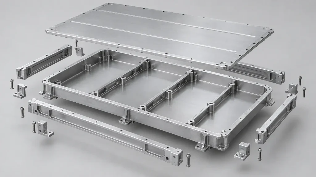
Complete Machined Housings vs. Secondary Machining
Machining from plate or billet can accommodate evolving prototype geometry without committing to dedicated casting tooling. It also allows several functional features to share a controlled datum system.
For a large tray, however, extensive pocketing creates material waste and demanding workholding. A near-net-shape structure with selective machining may deserve comparison. The Aluminum Association’s processing overview, under “Extrusions” and “Forming the end product,” explains that extruded profiles commonly undergo subsequent operations, including machining and welding.
| Starting route | Useful application | Machining contribution | Main planning concern |
|---|---|---|---|
| Plate or billet | Evolving prototype housings and mounting structures | Pockets, datums, sealing interfaces | Stock removal and released distortion |
| Extruded profiles | Perimeter rails and repeated cross-sections | Ends, holes, ports, interface pads | Profile variation and joining access |
| Castings | Integrated ribs, bosses, and complex near-net shapes | Critical bores, threads, sealing lands | Casting integrity and machining allowance |
| Formed or joined structures | Broad panels and fabricated tray assemblies | Selected mounting and mating surfaces | Joining movement and final setup access |
This is a process-selection framework, not a ranking of universally superior methods.
Before comparing prices, check the component envelope, handling requirements, and cutter access. A continuous flange may fit inside the machine’s travel while its assembled rails prevent the cutter or inspection probe from reaching the inner edge.
Machining Aluminum EV Battery Enclosures: Material and Stock Selection
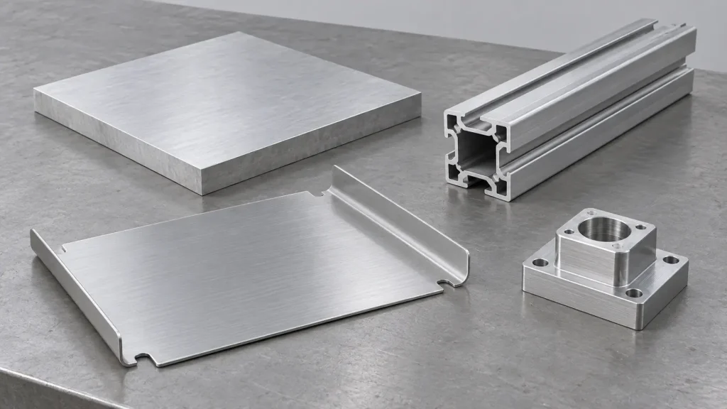
Match Alloy and Temper to the Manufacturing Route
6061 plate is a candidate for machined prototype structures, mounting plates, and interface components. Where extensive material removal makes stability important, evaluate an appropriate stress-relieved temper such as T651. The designation does not guarantee a distortion-free finished part.
Extruded rails require a product-form-specific specification. Candidates within the 6xxx family include 6061 and 6082, depending on profile availability, structural requirements, and joining plans.
Formed panels may instead favor suitable 5xxx-series sheet, such as 5052 or 5754. For designs considering 5052, the guide to 5052-H32 vs 6061-T6 sheet explains the trade-offs between forming requirements and material condition. Casting alloys require a separate selection process.
These are starting candidates, not interchangeable approvals. Confirm the complete alloy, temper, stock form, and material condition with the design owner.
Evaluate More Than Strength
The material review should include corrosion exposure, joining compatibility, and downstream finishing. An alloy selected for its delivered strength may have different local properties after welding. Likewise, a plate selected for machining stability may offer little advantage if a later operation changes its shape.
For a BOONA RFQ, our recommendation is to identify which features require their final relationship after joining. If the flange must be finished at that stage, reserve machining allowance and verify tool access before fixing the rail geometry.
Discuss stock selection and interface requirements through BOONA aluminum CNC machining services, rather than specifying only “aluminum” on the drawing.
Critical Interfaces: Sealing, Mounting, and Cooling
Sealing Flanges and Gasket Features
A sealing land needs a defined relationship to the cover, fasteners, and gasket. Review continuity around corners, potential scratch paths, and the available space for the seal to compress. Gasket geometry and compression requirements should come from the selected sealing system.
Specify whether battery tray flatness applies with the component released, supported at designated points, or restrained in an assembly. A surface-roughness value alone cannot describe flange waviness, cover stiffness, or compression between fasteners.
Module Supports and Vehicle Mounting Points
Module-location features and vehicle attachment points serve different load paths. Reference critical hole patterns and support heights to functional datums, rather than an easily measured cosmetic edge.
For removable modules, review insertion access and fastener engagement as well as final position. A threaded boss can meet its individual dimensions while leaving insufficient access for the intended assembly tool.
Cooling Interfaces and Coolant Boundaries
A tray supporting a separate cold plate has different requirements from a tray that forms part of the coolant circuit. Identify every pressure boundary and assign responsibility for closing and testing it.
Thermal-contact surfaces need a relationship to the selected interface material and assembly loading. Avoid imposing the same finish on all internal surfaces without a functional reason.
Pro Tip: Mark the coolant boundary and the environmental sealing boundary separately on the interface drawing. A passing cover-seal test does not establish coolant-circuit integrity.
For passages crossing a joint or machining setup, our DFM recommendation is to identify how each transition will be closed, inspected, and tested before finalizing the manufacturing sequence.
Controlling Distortion Through Machining and Joining
Thin Floors, Long Rails, and Unsupported Flanges
Material removal changes the balance of residual stress. Cutting forces and fixture pressure can also deflect a thin floor while the tool establishes its surface.
Plan roughing and finishing around the stiffness remaining at each stage. Retain support where practical, provide appropriate finishing allowance, and reassess the released geometry before committing to critical mating surfaces. Excessive clamp force can conceal movement until unloading.
Inspection planning should identify support locations and distinguish the part’s released geometry from its restrained assembly condition. Otherwise, machining and incoming inspection may assess different shapes.
Decide Which Features Need Post-Joining Machining
Finishing a sealing face before joining can leave that face vulnerable to later movement. Finishing afterward requires accessible datums, enough remaining stock, and support that does not distort the assembly.
No single sequence fits every enclosure. Coordinate joining, any specified thermal treatment, machining, and finishing before releasing the process plan.
Published Application: Straightening a Coolant-Channel Battery Tray
A 2023 battery-tray study documented by Oak Ridge National Laboratory examined aluminum plates friction-stir welded to a die-cast tray to close coolant channels.
The Abstract section reports welding-induced deviations reaching ±3 mm from the pre-weld geometry. Researchers investigated burnishing and coining to recover the shape, then used neutron diffraction to assess residual stress.
Both straightening approaches improved geometry, yet their stress outcomes differed. The abstract reports reduced residual stresses after burnishing, while coining increased the number of locations where stress exceeded yield strength.
This was independent research, not a BOONA project, and does not establish BOONA capability. It concerns a particular welded tray, not a universal machining allowance. The engineering inference is that restored shape and acceptable residual stress require separate consideration. A dimensional report alone cannot establish that a correction process restored the original material condition.
Surface Treatments, Electrical Interfaces, and Cleanliness
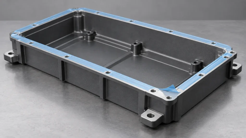
Specify Finishing by Surface Function
A blanket instruction such as “anodize all surfaces” can conflict with electrical bonding or precision fits. Identify areas requiring corrosion protection, controlled electrical contact, or tightly managed final dimensions.
Anodic oxide is electrically insulating, so bonding interfaces need a defined treatment or masking strategy. Uncoated contact areas also require a corrosion-management plan. Protective coatings should not automatically become the sole basis for high-voltage insulation claims.
Address dissimilar-metal interfaces at fasteners and inserts. Review the finish, joint environment, and isolation strategy together.
Control Chips, Burrs, and Residues
Aluminum battery tray machining can leave debris in blind holes, intersecting passages, or recessed corners. Plan deburring and cleaning access before those features become enclosed by joining.
A practical release rule is to inspect inaccessible regions before closure and control subsequent contamination. Cleaning after assembly cannot reliably compensate for an unreachable chip trap.
The drawing should distinguish acceptable edge treatment from changes that would damage a gasket seat or reduce an engagement feature. Packaging must then protect the surfaces already accepted. A spacer or protective cover should contact a noncritical region rather than rub across a sealing land during transport.
Machining Aluminum EV Battery Enclosures: Inspection and Cost
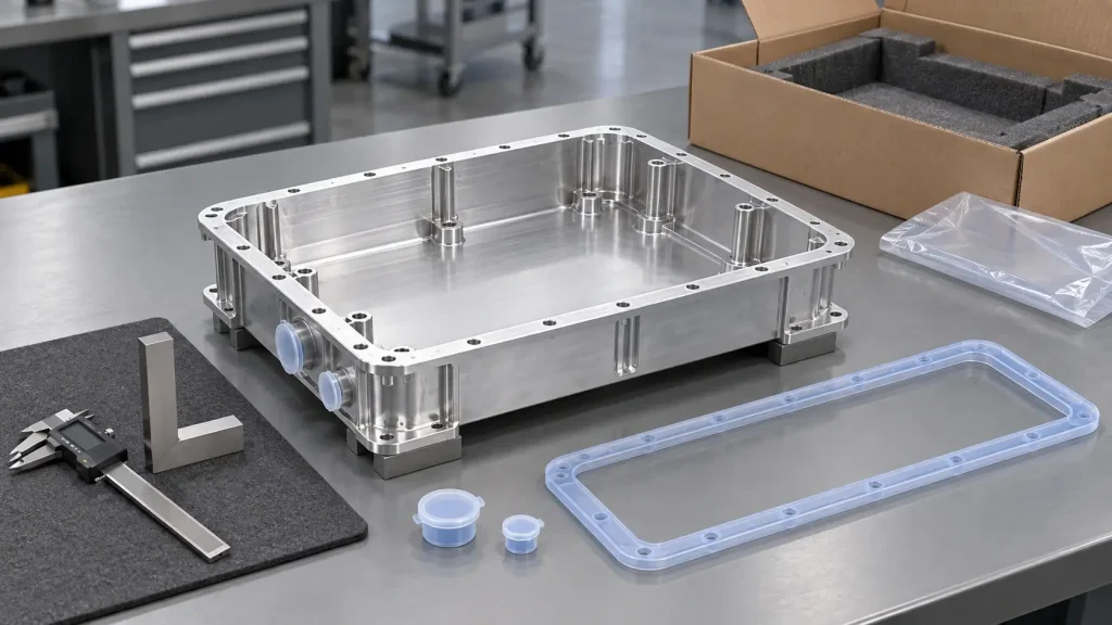
Match Acceptance to Delivery State
A quotation for an as-machined tray differs from one covering joining, finishing, and assembly testing. Use the following purchasing framework to define the handoff. These are delivery stages, not standardized quality grades.
| Delivery stage | Evidence to request | What remains outside that evidence |
|---|---|---|
| As machined | Material identity and dimensional results in the specified support condition | Effects of subsequent joining and finishing |
| After joining | Assembly geometry and agreed joint inspections | Final coating and complete sealing configuration |
| After finishing | Critical final dimensions, masking, and surface-condition checks | Performance of the complete assembled enclosure |
| Assembled and tested | Results for the specified configuration and test conditions | Unperformed pack-level or vehicle-level validation |
A 2024 study of mechanically joined battery-tray profiles illustrates why test boundaries matter. Section 4.4 and Figure 18 in the cited paper report leakage rates below 1 × 10⁻³ mbar·L/s for the investigated V6 joint specimens across the evaluated conditions.
The same section describes joining 600 mm profiles and testing 20 mm specimens removed from their centers. Those results do not represent a complete enclosure leak test.
This was not a BOONA project and does not establish BOONA capability. The engineering inference is to specify the actual boundary being tested, together with test medium, pressure differential, fixture sealing, and acceptance limit. Do not adopt the study’s limit as a universal battery-enclosure requirement.
What Drives the Quote?
Compare the cost of the accepted component, including fixtures, setup transfers, finishing, and inspection. Extensive material removal can outweigh a low blank price. A less expensive near-net shape can require more correction or complex holding.
Localize demanding requirements. A thermal-contact pad and a gasket land may justify different controls from a nonfunctional pocket floor. Keep assembly-level testing visible as a separate responsibility.
RFQ Checklist
Provide:
- CAD and a controlled drawing identifying functional datums.
- Alloy, temper, product form, and permitted substitutions.
- Mating-cover, seal, module, and coolant-interface information.
- Joining sequence and the condition in which dimensions apply.
- Finish and masking requirements, including electrical contact areas.
- Quantity, inspection evidence, testing ownership, and packaging needs.
If the design requires a particular machine envelope or inspection method, confirm suitability during quotation rather than inferring it from a general service description.
FAQs
Which aluminum alloys should be considered for EV battery trays?
Start with the manufacturing route. Machined plate components may use 6061; extrusion designs may evaluate suitable 6xxx alloys; formed panels may use selected 5xxx sheet. Confirm temper, joining effects, corrosion requirements, and structural suitability for the actual design.
Should a battery enclosure be machined from billet or fabricated?
Billet machining can support evolving geometry and integrated prototype features. Large, thin structures may justify fabricated or near-net-shape routes with selective machining. Compare tooling, stock removal, joining distortion, inspection, and anticipated design changes.
Why can an aluminum tray distort after machining or joining?
Material removal redistributes residual stress, while cutting and clamping can deflect flexible features. Joining introduces additional thermal or mechanical effects. The resulting geometry depends on the complete sequence, support arrangement, and measurement condition.
How should sealing-flange flatness be specified?
Define the sealing interface, mating component, and inspection state. State whether the part is released or restrained, and identify the supports where needed. Determine the allowable condition from the seal and cover design rather than copying a generic machining tolerance.
Does a machined aluminum enclosure automatically meet an IP rating?
No. Machining can create features intended to support an ingress-protection target. Establishing the rating requires evaluation of the specified assembled configuration, including its cover, seals, connectors, vents, and fastening condition.
What information is needed for a machining quotation?
Supply CAD, drawings, material specifications, quantity, and finishing requirements. Include mating geometry, critical interfaces, joining plans, and acceptance conditions. Separate component inspection from coolant testing, enclosure testing, and broader battery-pack validation.
Conclusion: Specify the Interfaces and Acceptance Conditions First
Machining Aluminum EV Battery Enclosures works best when material selection, process sequence, and acceptance conditions describe the same deliverable. Define what the tray supports, which surfaces seal, and whether cooling passages form part of its pressure boundary.
Then assign machining effort to the interfaces that need it. A prototype body, an extruded rail, and a joined production tray can require different routes even when they serve the same battery architecture. Increasing every tolerance requirement can add cost without addressing the feature that controls assembly performance.
Send your CAD, controlled drawing, and interface requirements to BOONA CNC machining service for a free DFM review. There is no minimum order quantity. Identify the delivery state and testing responsibilities so the quotation can address the requested components, without implying complete battery-pack certification.


