
“Vacuum-tight” appears on the drawing, but the quotation request never says whether the part ships as machined, cleaned, or leak-tested. Suppliers then price different scopes, and purchasing compares totals that cover different work. Machining Vacuum Chamber Components starts by defining those delivery conditions alongside the component’s vacuum function.
The essentials are controlled sealing geometry, a machining sequence that manages distortion, and acceptance criteria tied to the delivered condition. Buyers should specify the material, operating environment, seal details, and inspection requirements before comparing quotations.
Aluminum and stainless steel can both be appropriate. The choice depends on process compatibility and construction requirements, while completed-system vacuum performance remains an assembly-level responsibility.
Machining Vacuum Chamber Components Starts with Service Requirements
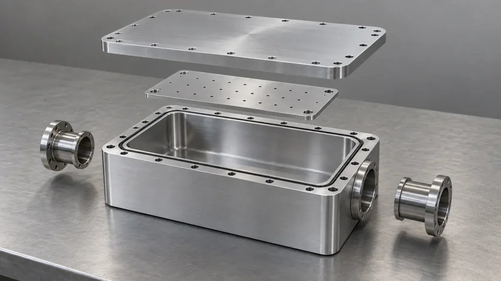
Identify the Component’s Function
A chamber body forms part of the vacuum boundary. An internal bracket supports hardware inside that boundary. An external mounting plate may never contact the evacuated environment.
Those distinctions change the drawing. Boundary components need defined seals and structural requirements. Internal parts need suitable materials, cleanable geometry, and a path for trapped gas to escape. External supports primarily need mechanical stability and reliable positioning.
State whether the supplier delivers an individual machined part, a joined subassembly, or hardware ready for a separately controlled cleaning operation.
Define the Operating Conditions
Give the target operating pressure under process conditions and the required base pressure under an agreed test condition. Include pump-down expectations, process gases, and temperature limits. Identify any bakeout, cryogenic cycling, or corrosive exposure.
Port geometry also matters. A narrow passage between the chamber and pump can restrict effective pumping speed, even when the pump itself has ample capacity.
For pressure-boundary components, identify the party responsible for external-pressure analysis and any applicable equipment rules. Machining to a drawing does not establish resistance to buckling. Large openings, unsupported lids, and loads from attached valves belong in that structural review.
Choosing Materials for Vacuum Chamber Components
Aluminum Versus Stainless Steel
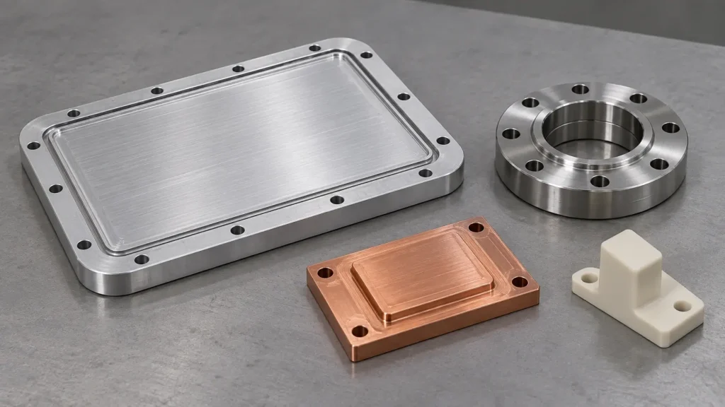
Aluminum vacuum chambers can offer useful weight and machining advantages. Stainless steel vacuum components often suit welded construction and environments requiring different corrosion or thermal characteristics.
Start with the exact grade and stock condition. “Aluminum” leaves temper unspecified; “stainless” leaves alloy selection unresolved. Material certificates should correspond to the supplied stock.
| Material | Typical component role | Manufacturing consideration | Application check |
|---|---|---|---|
| Aluminum 6061 | Bodies, lids, internal plates | Efficient machining; control stress release and weld effects | Process chemistry, temperature, and seal compatibility |
| Stainless steel 304L | Flanges and welded chamber parts | Cutting forces and joining sequence affect process planning | Corrosion exposure, magnetic requirements, and conditioning |
| Stainless steel 316L | Corrosion-sensitive chamber hardware | More demanding machining than aluminum | Confirm resistance to the actual media |
| Specified copper grade | Thermal links, electrical parts, selected sealing hardware | Soft material can smear or burr during cutting | Purity, thermal function, and interface design |
BOONA aluminum CNC machining service is relevant when the design calls for aluminum bodies or lids. Confirm the required material condition before establishing the machining sequence.
Copper and Nonmetallic Internal Parts
Copper’s thermal role can justify its use without making it the preferred material for the entire chamber. Likewise, a polymer support may provide electrical isolation while adding an outgassing consideration.
Qualify polymers, adhesives, and elastomers against temperature and contamination requirements. A material described as vacuum-compatible still needs a defined application and preparation condition.
Designing Sealing Surfaces, Flanges, and Ports
Match Geometry to the Sealing System
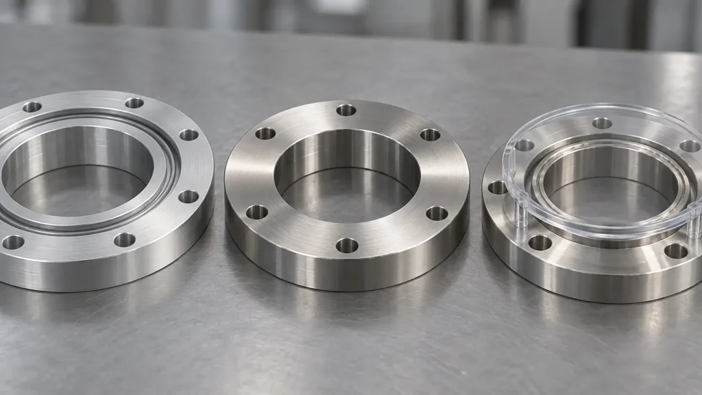
Elastomer O-ring glands and CF knife-edge interfaces require different machining controls. Groove geometry must suit the specified O-ring and assembly arrangement. A knife edge requires its intended profile and protection against local damage.
KF and ISO flange arrangements also depend on the correct mating hardware. Naming a flange family does not replace the controlled interface drawing.
Identify sealing faces, bolt patterns, and port axes together. A port that sits correctly by itself can still interfere with a neighboring valve body or prevent access to mounting fasteners.
Specify Surface Requirements Where They Matter
Surface roughness, flatness, and scratches describe different characteristics. A low average roughness value cannot establish that a sealing land is flat, undamaged, or free from a continuous machining mark crossing the seal.
Specify the required texture and form on the relevant surfaces. Include the measurement method where acceptance depends on it. Avoid extending a demanding seal-face requirement to every internal pocket without a functional reason.
Define edge treatment locally. A general “deburr all edges” instruction needs exceptions around deliberate knife edges and other functional profiles. Protective covers should contact robust areas rather than the sealing feature itself.
Planning the Machining Process
Control Distortion and Maintain Datum Relationships
Removing a deep pocket changes how a blank carries stress. Heavy clamping can temporarily flatten a flexible lid, hiding the shape it takes after release.
BOONA documented CNC machining approach separates bulk roughing from final finishing and uses low-force workholding on distortion-sensitive parts. These are general machining practices described by the company.
For a chamber lid, the engineering recommendation drawn from that approach is to check the part after roughing in its specified measurement condition before finishing the sealing face. If the drawing calls for free-state flatness, clamping the lid flat during measurement would conceal the condition being assessed. Stock condition and the remaining wall section determine the appropriate sequence.
Coordinate Structural and Manufacturing Decisions
For a welded blank, plan which interfaces need machining after joining. Welding can move a flange or change the relationship between mounting faces.
Multi-axis access can reduce transfers between fixtures for angled ports. Nevertheless, tool reach, holder clearance, and the inspection datum scheme still determine whether that approach helps.
Agree whether critical dimensions apply in the free state or under a defined restraint. If qualification includes thermal cycling, specify which measurements must follow it. Do not introduce an unapproved heat treatment that changes the ordered temper merely to simplify finishing.
Preventing Trapped Gas and Contamination
Distinguish Real Leaks, Virtual Leaks, and Outgassing
A real leak admits gas across the vacuum boundary. A virtual leak releases gas from a trapped volume through a restricted path. Outgassing releases gas from surfaces or the material itself.
A vented internal fastener can help empty a blind recess. The vent must remain within the approved vacuum-side geometry; drilling through the pressure boundary creates a different problem.
Material performance also depends on conditioning. In a 2025 CERN-authored stainless-steel study, Table IV reports room-temperature hydrogen outgassing of 1.0 × 10⁻¹⁵ mbar·L·s⁻¹·cm⁻² for AISI 444, compared with 7.2 × 10⁻¹³ for AISI 304L, after an 80°C, 48-hour bakeout.
These were cleaned sheet specimens for future gravitational-wave detector vacuum systems. The study was not a BOONA project and does not establish BOONA capability or finished-chamber performance. The engineering inference is to specify the gas species and preparation condition whenever comparing outgassing data.
Design for Cleaning and Clean Delivery
CERN’s surface-treatment guidance identifies inaccessible surfaces and holes that cannot be fully rinsed or dried as design problems. Plan access before closing passages or installing hardware.
The same BOONA machining FAQ describes dimensional compensation for anodizing. Applied to vacuum-part planning, that practice prompts a specific drawing check: approve coating compatibility and masking before defining the machining allowance. State whether each critical dimension applies before or after treatment. Dimensional compensation does not, by itself, establish that a coating suits the vacuum environment.
Pro Tip: Put the delivery condition beside the critical feature requirements. “After finishing and approved cleaning” defines a different handoff from “as machined.”
Inspection and Acceptance for Machining Vacuum Chamber Components
Verify Geometry and Surface Condition
The inspection plan should identify sealing-land form, groove dimensions, and port relationships. Match each characteristic to an appropriate measurement method.
Record the drawing revision and the manufacturing condition during inspection. A report generated before finishing cannot automatically establish the dimensions after material removal or coating growth.
Define Vacuum Testing Separately
“Helium tested” leaves too much open. Specify the test configuration, pressure differential, detection sensitivity, allowable leak rate, and reporting requirements. Identify whether the test covers an individual part, temporary closures, or a joined assembly.
Leak rate, outgassing rate, and operating pressure answer different questions. Pump-down and residual-gas measurements may therefore belong in the equipment builder’s acceptance plan even when component leak testing passes.
Application Example: Protecting an Optical Reference Cavity
A 2024 NIST-authored optical-reference-cavity study shows why acceptance can extend beyond sealing. Section II.C, “Vacuum design,” describes an inner chamber made from two aluminum halves with a spring-energized metal O-ring.
The same section reports optical finesse decreasing from 130,000 to 100,000 during a warmup. Finesse describes optical resonance performance, not a chamber leak rate. The authors discuss contamination collecting on the mirrors while the optical cavity remains the coldest object.
This is a laboratory frequency-metrology system, not a BOONA project or evidence of BOONA capability. It provides no universal machining tolerance.
The engineering inference is that cleanliness and temperature transitions can be part of functional acceptance. For the component buyer, that means asking how handling, trapped volumes, and assembly access affect the protected optics, rather than interpreting a leak-test result as complete system qualification.
Cost Drivers and the RFQ Checklist
Compare the Same Delivery State
Vacuum chamber machining costs increase with inaccessible features, substantial stock removal, and demanding form requirements. Special cleaning and test documentation introduce separate work.
Use an acceptance-state checklist to make quotations comparable:
| Quoted delivery state | Evidence to request | Boundary to clarify |
|---|---|---|
| As machined | Dimensional report and material identification | Later joining or finishing may change the part |
| After joining or finishing | Relevant reinspection and approved process records | Earlier measurements may need repeating |
| Cleaned and packaged | Agreed cleaning record and packaging method | Cleanliness depends on the specified procedure |
| Tested configuration | Test conditions, calibrated method, and results | Results apply to the documented configuration |
These states are a purchasing framework, not standardized quality grades, and an order can include several of them. A higher-priced quotation may simply include operations missing from another offer.
What Buyers Should Submit
Send the CAD model with the released drawing. Identify the vacuum boundary, critical seal details, and mating components. Specify material condition and quantity.
Include operating conditions, approved finishes, and cleaning instructions. State who supplies temporary test closures and who owns assembly-level validation.
Ask for separate pricing when requirements remain undecided. An optional finishing operation or leak-test scope is easier to compare as a defined line item. Avoid ordering additional polishing to compensate for an unresolved seal design.
FAQs
What material is best for vacuum chamber components?
There is no universal choice. Aluminum can suit weight-sensitive machined bodies; stainless steel can suit welded construction or different chemical environments. Select the grade against temperature, corrosion exposure, structural requirements, and preparation procedures.
Can CNC-machined aluminum support high-vacuum applications?
Yes, suitable aluminum components can form part of high-vacuum systems. Achievable performance depends on stock quality, interfaces, joining, cleaning, and conditioning. CNC machining alone does not assign a vacuum rating.
What surface finish is required for a vacuum seal?
Use the requirements of the selected seal and interface drawing. Evaluate roughness separately from flatness, scratches, and edge condition. A single finish value cannot cover elastomer glands and metal-gasket knife edges interchangeably.
How do blind holes create virtual leaks?
Gas trapped beneath a fastener can escape slowly through thread clearances. Approved internal venting can reduce that trapped volume. Review the route carefully so the vent does not cross the vacuum boundary.
Does helium leak testing prove UHV compatibility?
No. It evaluates leakage under defined conditions. Outgassing, permeation, contamination, and pumping performance remain separate considerations. An assembled system may require additional characterization.
What should a vacuum-component RFQ include?
Provide drawings, material condition, operating environment, seal details, and quantity. Add the intended delivery state, cleaning procedure, inspection requirements, and test responsibilities so suppliers price the same scope.
Conclusion: Specify the Vacuum Function Before Quoting the Part
Machining Vacuum Chamber Components works best when the drawing defines the component’s function and the quotation defines its delivery condition. Specify the seal before selecting its finish. Coordinate roughing, joining, and final machining around distortion risk.
The acceptance-state checklist gives purchasing and engineering teams a common basis for comparison. Keep dimensional conformity, component leak testing, and completed-system performance separate. Assign responsibility for each before manufacturing starts, especially where another supplier will add coatings, weld connections, or perform final cleaning.
A clear drawing should also identify which requirements remain open. Those unresolved items deserve an agreed decision before they become irreversible machining choices.
Send BOONA your CAD model, controlled drawing, and vacuum-service requirements for a review through its precision CNC machining services. There is no minimum order quantity, and every quote includes a free DFM review. Confirm any specialized cleaning or vacuum-testing scope during quotation. Send your CAD to begin the technical discussion.


