
A 3D printed part can look beautiful on a desk and still fail during assembly. It can also be strong enough for testing but too rough, bulky, or unfinished for a customer presentation. That is the real challenge behind 3D printing design optimization: the part has to do its job, but it also has to look like it belongs in a real product.
This balance is especially important in product development. A designer may care about the surface, curve, texture, and overall feel. An engineer may care about wall thickness, load direction, snap-fit strength, heat resistance, and dimensional accuracy. A purchasing manager may care about cost and delivery time. The final 3D printed part has to satisfy all of them, or at least make the right compromise.
In most projects, the question is not “Should we design for strength or aesthetics?” The better question is: which areas need strength, which surfaces need appearance quality, and which features need both?
That is where professional custom 3D printing services become valuable. The CAD file may define the shape, but process selection, orientation, material choice, and finishing strategy often decide whether the part is actually useful.
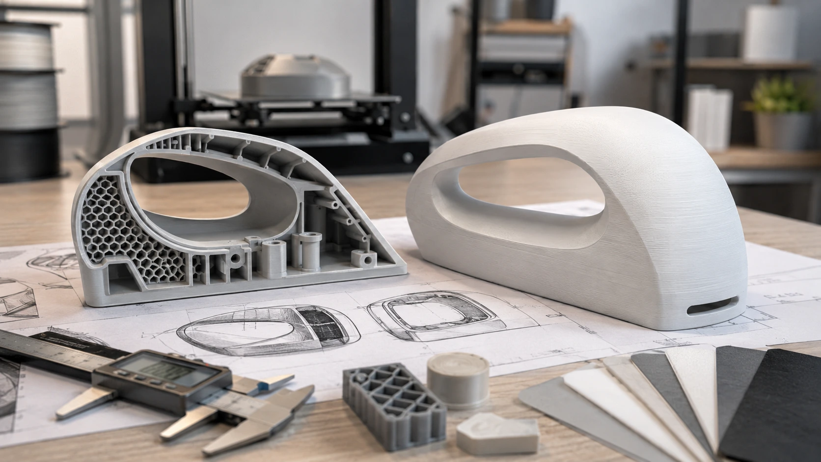
Why Strength and Aesthetics Often Fight Each Other
In theory, a strong part and a good-looking part should be the same thing. In reality, 3D printing makes the trade-off more complicated.
A stronger design often needs thicker walls, larger radii, ribs, gussets, reinforced bosses, and enough material around screw holes or clips. These details help the part survive handling, bending, assembly, and impact. But if they are placed carelessly, they can make the part look heavy or leave visible marks on cosmetic surfaces.
A more attractive design usually wants clean outside surfaces, slim walls, sharp product lines, smooth curves, and hidden mechanical features. That may look great in a rendering, but it can create weak corners, thin snap-fits, fragile clips, or warped flat panels after printing.
For example, a thin handheld device housing may look elegant in CAD. But if the wall is only 0.8 mm thick and the screw bosses are not reinforced, the prototype may crack when the first screw is installed. On the other hand, if every wall is made 4 mm thick “for safety,” the part becomes heavy, expensive, and less like the final product.
Good 3D printed part strength optimization is not about adding plastic everywhere. It is about adding material where the load actually goes.
Start With the Part’s Purpose, Not the Printing Process
One common mistake is choosing the printing process too early. Someone may say, “Let’s use SLA because it looks smooth,” or “Let’s use MJF because it is stronger.” That may be right, but only after the part’s purpose is clear.
Before choosing SLA, SLS, MJF, FDM, or metal printing, ask a few practical questions:
Will this part be used only for visual review?
Will someone assemble it with screws, clips, or inserts?
Will it be dropped, bent, heated, or loaded?
Does the customer need to touch it and judge the surface?
Are there mating features that need tight tolerance?
Is this a one-off prototype or a small production batch?
A display model and a functional test part should not always be printed the same way. Boona’s 3D printing technology article also separates SLA, SLS, and MJF by use case: SLA for visual appeal and detail, SLS for durable nylon parts, and MJF for speed and scalable production.
Here is a more realistic way to think about it:
| Project Situation | What Matters Most | Better Starting Point |
|---|---|---|
| Product appearance model for a meeting | Smooth surface, detail, paint quality | SLA or MJP |
| Snap-fit housing for repeated testing | Toughness, clips, assembly strength | SLS or MJF |
| Large concept model | Size, cost, quick visual check | FDM |
| Functional bracket or fixture | Stiffness, durability, load direction | SLS, MJF, or engineering FDM |
| Metal part with complex internal geometry | Heat, load, complex shape | DMLS / metal 3D printing |
| Prototype with tight holes or mating faces | Accuracy in selected areas | 3D printing + CNC machining |
This is why SLA vs SLS vs MJF for functional prototypes is not just a material question. It is a design-intent question.
Material Choice: The First Real Compromise
Material selection has a direct impact on strength, appearance, cost, and finishing. A resin part may look excellent, but it may not behave like a production plastic under load. A nylon powder-bed part may be tougher, but the surface texture may not look as polished without finishing.
For a practical 3D printing design optimization guide, material selection should be tied to how the part will be used.
| Material / Process | Strength Behavior | Appearance Level | Common Use |
|---|---|---|---|
| SLA resin | Good detail, moderate functional strength | Very smooth | Visual prototypes, fit models, painted samples |
| SLS PA12 nylon | Tough, durable, good for complex shapes | Slightly grainy | Functional prototypes, clips, brackets |
| MJF PA12 nylon | Strong, consistent, production-friendly | Good after finishing | End-use nylon parts, small batches |
| FDM ABS / ASA | Practical strength, visible layer lines | Medium | Large prototypes, fixtures, housings |
| TPU | Flexible and impact-absorbing | Medium | Seals, grips, soft components |
| DMLS metal | High strength and heat resistance | Needs finishing for better appearance | Metal prototypes, aerospace, tooling inserts |
If the part is only for a photo shoot or investor demo, an SLA printed and painted part may be the best choice. If the same part needs to survive assembly testing, SLS or MJF may be closer to real-world use. For projects that need multiple versions, it is often smarter to print one appearance prototype and one functional prototype instead of forcing one part to do everything.
That may sound like extra cost, but it often saves time. A beautiful but weak prototype gives misleading feedback. A strong but ugly prototype may fail a design review. Two targeted prototypes can answer two different questions faster.
Wall Thickness: Where Many 3D Printed Parts Go Wrong
Wall thickness is one of the easiest design details to underestimate. A thin wall can make a model look sleek, but it may also warp, crack, or feel cheap in the hand. A thick wall may improve stiffness, but it increases print time, material use, and sometimes distortion.
For most plastic 3D printed prototypes, these are practical starting points:
| Feature | Visual Prototype | Functional Prototype | End-Use / Low-Volume Part |
|---|---|---|---|
| General wall thickness | 0.8–1.2 mm | 1.5–2.5 mm | 2.0–3.0 mm |
| Small ribs | 0.6–1.0 mm | 1.0–1.8 mm | 1.5–2.5 mm |
| Screw boss outer wall | 1.5–2.0 mm | 2.0–3.5 mm | 3.0 mm+ or insert-ready |
| Minimum fillet radius | 0.5 mm | 1.0–2.0 mm | 1.5–3.0 mm |
| Clearance for assembled parts | 0.2–0.4 mm | 0.3–0.6 mm | Test and adjust by process |
These numbers are not universal rules. They are starting points. SLA, SLS, MJF, and FDM do not behave the same way. Part size, geometry, tolerance, and post-processing all affect the final decision.
Boona’s rapid prototyping information mentions 3D printing parameters such as ±0.2 mm tolerance, 0.6 mm minimum wall thickness, and 50–300 μm layer height for rapid prototype work. Those numbers are useful references, but functional parts usually need more than the minimum wall thickness.
A simple rule works well: use the minimum wall only for non-critical details, not for clips, bosses, mounting points, hinges, or load-bearing areas.
Print Orientation Can Decide Whether the Part Fails
Print orientation is easy to ignore because it is not always visible in the CAD model. But once the part is printed, orientation affects strength, layer lines, support marks, and dimensional stability.
For FDM parts, the issue is obvious: parts are usually weaker between layers than along continuous extruded paths. For powder-bed and resin processes, orientation still matters because it affects surface finish, support placement, heat behavior, and accuracy.
A part can be technically printable in several directions, but only one direction may make sense for the final use.
| Orientation Choice | Strength Result | Appearance Result | Typical Risk |
|---|---|---|---|
| Printed flat | Stable and efficient for many parts | Visible layer stepping on vertical faces | Large flat areas may warp |
| Printed upright | Can improve side appearance | Layer direction may weaken bending areas | Higher risk of breakage under load |
| Printed at an angle | Can improve curved surfaces | Support marks may increase | More post-processing |
| Oriented around critical features | Better functional result | Cosmetic surfaces can be protected | Needs DFM review |
For a bracket, orient the part so the main load does not pull directly across weak layer boundaries. For a cosmetic housing, place supports on the inside or hidden surfaces. For a part with a critical hole, consider whether that hole should be printed, reamed, or machined after printing.
This is where rapid prototyping services are useful. A prototype should not only show the shape; it should reveal whether the orientation and design choices are practical before the project moves forward.
How to Improve Strength Without Making the Part Ugly
The best structural features are often the ones the customer never sees. Internal ribs, hidden gussets, thicker bosses, and rounded transitions can make a part stronger without changing the outside appearance.
For functional 3D printed parts, these design moves usually work better than simply increasing the whole wall thickness:
| Weak Area | Better Design Fix | Why It Works |
|---|---|---|
| Sharp inside corner | Add a fillet | Reduces stress concentration |
| Long flat wall | Add internal ribs | Improves stiffness without thickening the whole wall |
| Screw boss cracking | Add base fillet and thicker boss wall | Spreads assembly load |
| Snap-fit breaking | Use larger root radius and tougher material | Reduces brittle failure |
| Thin mounting tab | Increase width or add gusset | Improves bending resistance |
| Hole near edge | Move hole inward or add local reinforcement | Prevents splitting |
A well-designed rib can be more effective than a thick wall. A 2 mm wall with properly placed ribs may feel stronger than a 4 mm wall with no support. It also prints faster and looks closer to a production part.
This approach is especially useful for enclosures, handheld devices, drone parts, brackets, automotive interior prototypes, and medical device housings.
How to Keep the Part Looking Like a Real Product
Appearance is not just about smoothness. A good-looking prototype has controlled edges, believable proportions, clean surfaces, and the right finish for its purpose.
For aesthetic 3D printed prototypes, designers should think about finishing before printing starts. Sanding, painting, dyeing, bead blasting, and vapor smoothing all affect the final surface. If the design has tiny raised details, deep narrow grooves, or fragile edges, finishing may damage them.
Good cosmetic design usually includes:
Smooth outer faces with hidden structural features
Small edge radii instead of knife-sharp corners
Support marks placed on non-visible surfaces
Enough wall thickness to avoid warping
Flat areas designed to reduce distortion
Surface finish specified before production
Clear separation between cosmetic surfaces and functional features
Boona provides surface finishing options for prototype and low-volume parts, including processes such as painting, polishing, bead blasting, electroplating, and other finish treatments depending on the material and application.
For a product housing, the outside may need SLA-level smoothness and paint. But the internal structure may need SLS or MJF-style strength. In that situation, it may be better to split the design into separate test builds rather than expecting one prototype to answer every question.
When CNC Machining Should Be Added After 3D Printing
3D printing is excellent for complex geometry, but it is not always the best way to achieve tight tolerance. If a part has a bearing seat, sealing face, threaded hole, press-fit hole, or precision mating surface, secondary machining may be necessary.
A hybrid workflow can look like this:
- Print the complex body.
- Stress relieve or clean the part if needed.
- CNC machine the critical holes, faces, or interfaces.
- Finish the surface for appearance or function.
- Inspect the part against the drawing.
This approach is especially useful for metal 3D printed parts, functional fixtures, and high-value prototypes. Boona also offers precision CNC machining services, which makes sense when a 3D printed part needs tighter features than printing alone can reliably provide.
A practical example is a lightweight bracket with organic geometry. The overall shape may be printed, but the mounting holes can be machined afterward to improve fit and assembly repeatability.
A Realistic Design Example: Product Housing Prototype
Imagine a small electronics housing for a new handheld device. The sales team wants a clean appearance for customer feedback. The engineering team wants to test clips, screw bosses, and internal component clearance. The purchasing team wants the fastest practical prototype.
A weak design would use thin walls everywhere, sharp internal corners, small snap-fits, and cosmetic surfaces that need heavy support. It may look fine in a render, but the printed part may crack, warp, or show marks in the wrong places.
A better design would separate appearance and function:
| Design Area | Optimization Choice |
|---|---|
| Outer shell | Smooth surfaces, small edge radii, support-free visible faces |
| Internal ribs | Hidden reinforcement behind flat panels |
| Screw bosses | Larger base fillets, thicker local walls |
| Snap-fits | Tougher material, rounded roots, realistic clearance |
| Display surface | Oriented to reduce visible stepping |
| Assembly holes | Printed oversized or machined after printing if needed |
| Finish | Sanding and painting for appearance model; MJF/SLS for functional test |
In this case, SLA may be used for a visual model, while SLS or MJF may be used for clip and assembly testing. If the part later moves toward a small production run, low-volume manufacturing services can help bridge the gap between prototype validation and production supply.
Quick Checklist Before Sending a 3D Printing File
Before uploading the CAD file, it is worth checking the part with two questions: “Will it survive?” and “Will it look right?”
| Checkpoint | Why It Matters |
|---|---|
| Are load-bearing areas thick enough? | Prevents cracking and bending failure |
| Are internal corners filleted? | Reduces stress concentration |
| Are cosmetic faces protected from supports? | Improves appearance |
| Is the material suitable for testing? | Avoids misleading prototype results |
| Are screw bosses reinforced? | Improves assembly reliability |
| Are tolerances realistic for the process? | Reduces rework |
| Is post-processing planned? | Prevents surprise dimensional or surface changes |
| Are critical features marked on a drawing? | Helps the manufacturer quote and inspect correctly |
This kind of review is the difference between “a printed model” and a useful engineering prototype.
Final Thoughts
3D printing design optimization is not about choosing strength over aesthetics or aesthetics over strength. It is about understanding what the part must prove.
If the part is for a design review, surface quality and presentation matter most. If it is for assembly testing, clips, bosses, wall thickness, and material toughness matter more. If it is for low-volume use, the design must balance durability, finish, tolerance, and repeatability.
The best 3D printed parts are not usually the ones with the most material or the smoothest surface. They are the parts where every design choice has a reason: the wall thickness supports the load, the orientation protects the key surface, the material matches the test, and the finish supports the final use.
For companies developing prototypes, housings, fixtures, brackets, or end-use components, working with an experienced 3D printing and rapid prototyping partner can reduce trial-and-error and help the design move from CAD to a real, testable product faster.


