
C110 copper is one of the most widely used copper grades for electrical and thermal components. It is specified for parts such as busbars, battery terminals, heat sinks, grounding blocks, RF components, power distribution hardware, and high-conductivity connectors. On paper, it looks like an ideal engineering material: high copper purity, excellent electrical conductivity, strong thermal transfer, and good corrosion resistance.
On the CNC machine, however, C110 copper can be frustrating.
Unlike aluminum, brass, or free-machining steel, C110 copper does not always break into clean chips. It is soft, ductile, sticky, and often described by machinists as “gummy.” If the cutting edge is not sharp enough, the material smears instead of shearing. If the feed is too light, the tool rubs. If coolant and chip evacuation are poor, copper can weld to the flute, causing built-up edge, burrs, chatter, dimensional drift, and poor surface finish.
That is why best CNC speeds and feeds for C110 copper should never be treated as a simple chart lookup. The right starting point depends on tool geometry, machine rigidity, coolant delivery, workholding, hole depth, part tolerance, and whether the operation is roughing, finishing, drilling, or turning.
For engineers sourcing custom copper CNC machining, the goal is not simply to remove material quickly. The real goal is to produce stable, burr-controlled, high-conductivity copper parts that meet dimensional, cosmetic, and functional requirements.
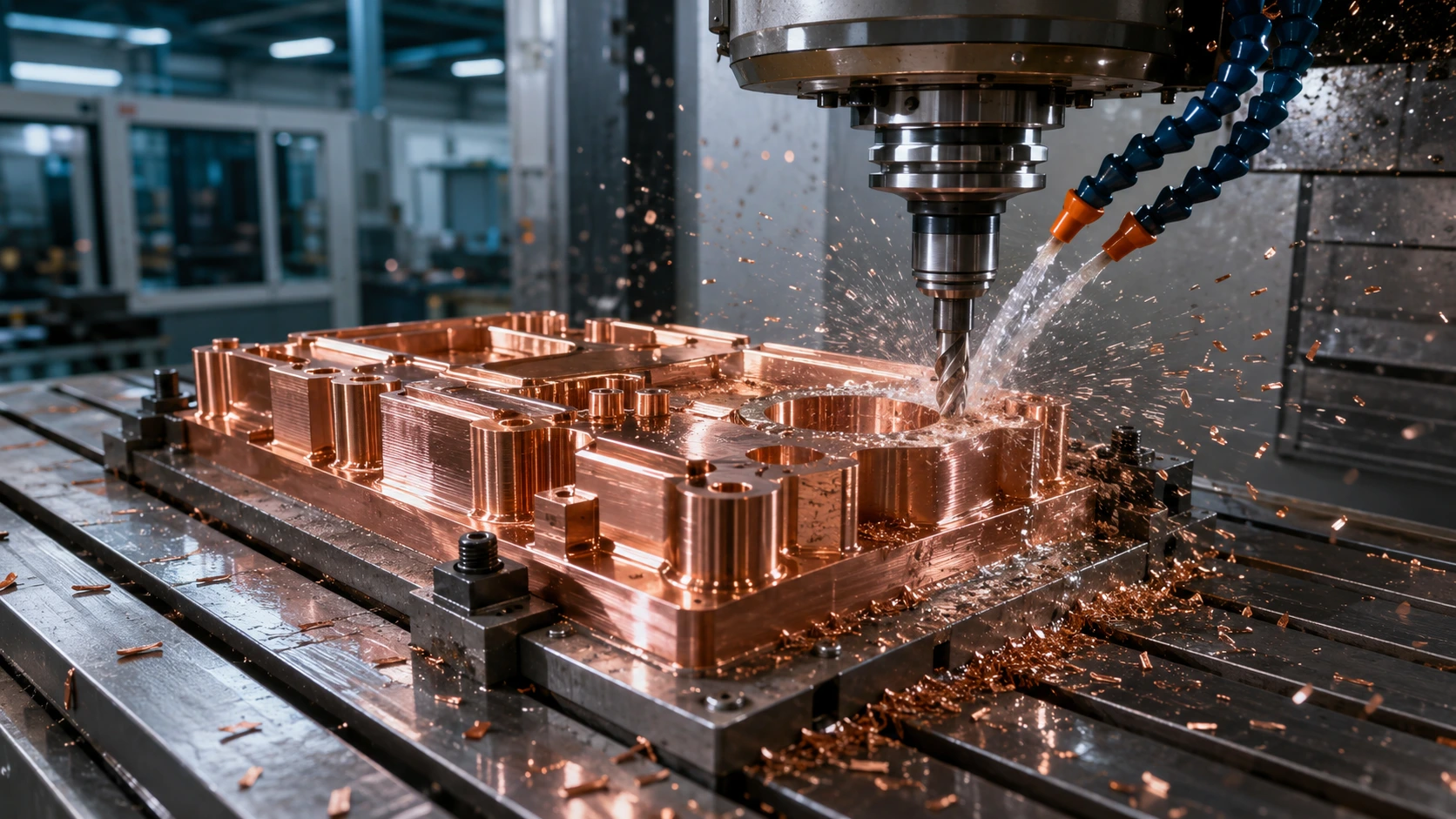
What Makes C110 Copper “Gummy”?
C110 copper, also known as electrolytic tough pitch copper, is a high-conductivity copper grade commonly used in electrical applications. Compared with brass or aluminum, it has much lower machinability because it is highly ductile and tends to deform plastically under cutting pressure.
The main machining challenges include:
| Machining Issue | What Happens in C110 Copper | Result on the Part |
|---|---|---|
| Built-up edge | Copper sticks to the tool edge | Rough finish, poor accuracy |
| Stringy chips | Chips do not break cleanly | Chip wrapping, tool damage |
| Burr formation | Soft edges deform during cutting | Extra deburring time |
| Tool rubbing | Feed is too light or tool is dull | Heat, smearing, work hardening |
| Chip recutting | Chips stay in slots or pockets | Scratches, poor finish |
| Thermal movement | Heat transfers quickly through copper | Size variation during inspection |
This is also why CNC machining pure copper custom parts often requires more careful process planning than machining brass or aluminum. The material is valuable because of its conductivity, but the same softness and ductility that make it useful also make it harder to machine cleanly.
C110 Copper Material Profile for CNC Machining
Before selecting C110 copper milling parameters, it helps to understand the material’s basic properties.
| Property | Typical C110 Copper Value | Machining Impact |
|---|---|---|
| Copper content | 99.90% minimum | High conductivity, low alloying content |
| Electrical conductivity | 100% IACS minimum | Excellent for electrical parts |
| Thermal conductivity | Around 388 W/m·K | Heat moves quickly through the part |
| Machinability rating | Around 20% compared with free-cutting brass | Requires sharp tools and careful feeds |
| Common applications | Busbars, heat sinks, terminals, connectors | Requires tight tolerances and clean surfaces |
| Main machining problem | Gummy, ductile chip behavior | Built-up edge and burr control are critical |
For projects where material choice is still open, it is worth comparing C110 with C101 and brass before finalizing the drawing. Boona article on CNC machining C101 vs C110 copper for electrical parts is a useful internal reference for engineers deciding between oxygen-free copper and electrolytic tough pitch copper.
Recommended Cutting Tool Geometry for C110 Copper
The first rule of machining gummy C110 copper is simple: use the sharpest practical cutting edge.
C110 copper does not respond well to dull tools, large edge hones, or general-purpose cutters designed for steel. A blunt edge pushes the copper instead of cutting it. That increases heat, smearing, burrs, and tool loading.
Recommended tooling features:
| Tool Feature | Recommended Choice | Why It Helps |
|---|---|---|
| Tool material | Carbide, polished carbide, PCD for high-volume work | Maintains sharp edge and wear resistance |
| Coating | Uncoated polished carbide, DLC, diamond coating | Reduces copper adhesion |
| Rake angle | High positive rake | Encourages clean shearing |
| Flute finish | Polished flute | Improves chip evacuation |
| Flute count | 2-flute or 3-flute for milling | More chip space for gummy material |
| Helix angle | High helix when rigidity allows | Pulls chips out more smoothly |
| Edge prep | Minimal hone, sharp edge | Prevents rubbing and smearing |
For production copper work, DLC-coated tools can be a strong option because they reduce friction and help prevent copper from welding to the cutting edge. For prototype or low-volume work, a sharp polished carbide tool is often the most practical starting point.
Best CNC Milling Speeds and Feeds for C110 Copper
The following table provides practical starting ranges for feeds and speeds for pure copper using carbide end mills. These are not final values for every machine. They are starting parameters that should be adjusted based on spindle power, tool runout, coolant pressure, part rigidity, and surface finish requirements.
Starting Milling Parameters for C110 Copper
| Tool Diameter | Surface Speed | Chip Load per Tooth | Radial DOC | Axial DOC | Best Use |
|---|---|---|---|---|---|
| 1/8 in / 3 mm | 300–600 SFM | 0.0008–0.0015 in/tooth | 5–15% D | 0.5–1.5×D | Small pockets, detail features |
| 1/4 in / 6 mm | 400–800 SFM | 0.0015–0.0030 in/tooth | 10–25% D | 0.5–2×D | General roughing and profiling |
| 3/8 in / 10 mm | 400–900 SFM | 0.0025–0.0045 in/tooth | 10–30% D | 0.5–2×D | Medium pockets and contours |
| 1/2 in / 12 mm | 500–1,000 SFM | 0.0030–0.0060 in/tooth | 10–30% D | 0.5–2×D | Stable roughing and finishing |
For most C110 copper CNC machining, avoid extremely light chip loads. A common mistake is reducing the feed too much because the material feels soft. In reality, too little feed causes rubbing. Rubbing creates heat, built-up edge, and smeared surfaces.
A better strategy is to keep the tool cutting with a real chip load while controlling engagement and chip evacuation.
Rough Milling Strategy for Gummy C110 Copper
When roughing C110 copper, the safest approach is usually not full-width slotting. Full slotting traps chips, increases heat, and makes stringy chip wrapping more likely. Adaptive or trochoidal toolpaths are usually more stable.
Recommended roughing approach:
| Parameter | Recommended Starting Point |
|---|---|
| Tool type | Sharp 2-flute or 3-flute carbide end mill |
| Toolpath | Adaptive clearing or trochoidal milling |
| Radial engagement | 10–25% of tool diameter |
| Axial engagement | 0.5–2× tool diameter |
| Coolant | Flood coolant or strong air plus lubricant |
| Chip control | Avoid recutting; clear chips continuously |
| Finish stock | Leave 0.10–0.30 mm for finishing |
This strategy works especially well for copper housings, busbar pockets, electrical contact blocks, and heat-dissipation components. If the part has thin walls or a long unsupported section, reduce radial engagement first before reducing feed per tooth.
Boona precision CNC machining services page lists capabilities for 3-axis, 4-axis, and 5-axis machining, which is useful for complex copper parts where tool access and chip evacuation must be planned carefully.
Finish Milling Parameters for Better Surface Quality
Finishing C110 copper is not just about slowing down. In many cases, going too slow makes the surface worse because the cutter rubs and smears the copper.
Finish Milling Starting Parameters
| Finish Operation | Recommended Value |
|---|---|
| Surface speed | 600–1,200 SFM |
| Chip load | 0.001–0.003 in/tooth |
| Radial stock | 0.05–0.20 mm |
| Axial finish pass | Light, stable engagement |
| Tool type | New or dedicated polished carbide tool |
| Coolant | Flood coolant or mist lubrication |
| Preferred direction | Climb milling when setup is rigid |
For cosmetic surfaces, use a dedicated finishing tool that has not been used for roughing. Copper adhesion on a roughing tool can ruin the final pass, even if the tool still looks usable.
If the part needs additional cosmetic or functional treatment, Boona surface finishing services page can be used as a natural internal link when discussing polishing, appearance improvement, and post-machining finish control.
Best Drilling Speeds and Feeds for C110 Copper
Drilling C110 copper requires special attention because gummy chips can pack inside the hole. Once chips stop evacuating, the drill can grab, smear the hole wall, or break.
C110 Copper Drilling Parameters
| Drill Type | Surface Speed | Feed per Revolution | Notes |
|---|---|---|---|
| HSS twist drill | 100–250 SFM | 0.001–0.006 in/rev | Use sharp drills only |
| Carbide drill | 200–500 SFM | 0.002–0.010 in/rev | Better for repeatability |
| Parabolic flute drill | 150–400 SFM | 0.002–0.008 in/rev | Good for deeper holes |
| Micro drill | 80–200 SFM | Light feed, controlled peck | Runout control is critical |
For C110 copper drilling speeds, the key is chip evacuation. Deep holes should use peck drilling or through-coolant drilling where possible. However, avoid excessive pecking that allows the tool to rub each time it re-enters the cut.
Practical drilling tips:
- Use sharp drills with polished flutes.
- Apply coolant directly into the hole.
- Use a controlled peck cycle for deep holes.
- Reduce spindle runout before drilling small holes.
- Avoid dwelling at the bottom of blind holes.
- Ream critical holes after drilling if tolerance and finish require it.
For threaded copper parts, select taps carefully. Spiral flute taps are useful for blind holes because they pull chips upward. Spiral point taps work well for through holes. Form taps can also work in ductile copper, but hole size must be controlled correctly because forming displaces material instead of cutting it.
Best CNC Turning Speeds and Feeds for C110 Copper
For turned C110 copper components such as terminals, pins, sleeves, threaded connectors, and conductive shafts, insert geometry matters as much as speed.
Use polished, sharp, positive-rake inserts designed for non-ferrous materials. Avoid inserts with heavy edge prep because they increase cutting pressure.
C110 Copper Turning Parameters
| Turning Operation | Surface Speed | Feed Rate | Depth of Cut | Tooling Recommendation |
|---|---|---|---|---|
| Rough turning | 400–900 SFM | 0.004–0.012 in/rev | 0.5–2.5 mm | Sharp positive-rake insert |
| Finish turning | 600–1,200 SFM | 0.002–0.006 in/rev | 0.1–0.5 mm | Polished non-ferrous insert |
| Grooving | 250–600 SFM | Based on tool width | Light to moderate | Use strong coolant flow |
| Parting | 200–500 SFM | Stable, moderate feed | Full cutoff | Keep tool square and sharp |
| Threading | 150–400 SFM | Thread-dependent | Light passes | Use sharp threading insert |
For C110 copper turning feeds, do not baby the cut too much. A feed that is too light can produce a shiny but dimensionally unstable smeared surface. A moderate feed with a sharp insert usually gives a better result.
Boona CNC turning service can be used as an internal link when discussing turned copper pins, threaded terminals, cylindrical electrical contacts, and custom conductive shafts.
Coolant and Lubrication: A Major Factor in Copper Machining
Coolant is not optional for many C110 copper operations. It helps in three ways: reducing adhesion, removing heat, and pushing chips away from the cutting zone.
| Cooling Method | Best For | Limitation |
|---|---|---|
| Flood coolant | Milling, drilling, turning | Requires good machine enclosure |
| High-pressure coolant | Deep holes, chip evacuation | Machine-dependent |
| Mist coolant / MQL | Light milling and finishing | Less chip flushing power |
| Air blast | Open profiling and dry setups | No lubrication |
| Cutting oil | Tapping, reaming, manual operations | Slower and messier |
For gummy copper, lubrication is especially important because built-up edge is often caused by copper sticking to the tool. A sharp tool plus proper lubrication usually improves surface finish more than simply changing spindle speed.
Common Problems When Machining C110 Copper and How to Fix Them
| Problem | Likely Cause | Practical Fix |
|---|---|---|
| Built-up edge on tool | Tool is dull, feed too light, poor lubrication | Use sharper polished tool, increase chip load, add coolant |
| Burrs on edges | Excess tool pressure or dull cutter | Use sharp tool, add finish pass, improve exit strategy |
| Stringy chips | Low chip load or poor chip-breaking geometry | Increase feed slightly, change toolpath, improve evacuation |
| Poor surface finish | Chip recutting, runout, rubbing | Check runout, use coolant, replace finishing tool |
| Hole wall smearing | Drill rubbing or chips packing | Use sharper drill, peck cycle, better coolant |
| Dimensional variation | Heat, built-up edge, unstable workholding | Let part cool, inspect tool, improve clamping |
| Tool grabbing | Too much engagement or poor chip clearance | Reduce radial DOC, use adaptive toolpath |
A strong quality system matters because copper parts often serve electrical, thermal, or safety-related functions. Boona quality control page is a useful internal reference when discussing dimensional inspection, CMM inspection, material certificates, and first article inspection.
Example Parameter Set for a C110 Copper Busbar Prototype
The following example shows a practical starting point for a machined C110 copper busbar with pockets, mounting holes, and a flat contact surface.
| Feature | Tool | Starting Parameters |
|---|---|---|
| Outer profile | 6 mm 3-flute carbide end mill | 600 SFM, 0.0025 in/tooth, 20% radial DOC |
| Pocket roughing | 6 mm polished carbide end mill | 500–700 SFM, 0.002–0.003 in/tooth |
| Finish contour | 6 mm sharp finishing end mill | 800 SFM, 0.0015–0.0025 in/tooth |
| Mounting holes | Carbide drill | 250–400 SFM, controlled peck |
| Chamfers | Sharp carbide chamfer mill | Light feed, avoid dwell |
| Flat contact face | Fly cutter or face mill for non-ferrous metals | High positive rake, flood coolant |
For a prototype job, the first part should be used to validate chip shape, burr level, surface finish, and flatness before scaling into batch production. For small to medium orders, Boona low-volume manufacturing services page is a natural internal link because C110 copper parts are often produced in prototype-to-batch quantities before full production release.
Design Tips to Improve C110 Copper Machinability
Good design can reduce machining cost and improve part quality. When possible, engineers should consider the following before releasing drawings.
| Design Feature | Better Practice | Why It Helps |
|---|---|---|
| Internal corners | Use larger radii | Reduces tool pressure |
| Thin walls | Avoid overly thin copper ribs | Prevents vibration and distortion |
| Deep narrow slots | Add clearance or split features | Improves chip evacuation |
| Tight tolerances | Apply only where functional | Reduces machining and inspection time |
| Threaded holes | Use realistic depth | Reduces tap breakage risk |
| Contact faces | Define flatness and finish clearly | Improves electrical performance |
| Burr-sensitive edges | Add controlled chamfers | Reduces manual deburring |
If the project is still in the material selection stage, link to Boona material list so readers can compare C110 copper with C101 copper, brass, aluminum, and other engineering metals.
When Should You Choose C110 Copper Instead of Brass or C101?
C110 copper is usually the right choice when the part needs excellent conductivity but does not require oxygen-free copper for vacuum, brazing, or reducing-atmosphere exposure.
Choose C110 copper for:
- Electrical busbars
- Conductive terminals
- Grounding blocks
- Battery connectors
- Power distribution parts
- Heat transfer plates
- Copper heat sinks
- General conductive CNC parts
Choose C101 copper when oxygen-free performance is required. Choose brass when machinability and cost matter more than maximum conductivity. Boona article on copper vs brass CNC machining for high precision parts is a good supporting link for readers comparing conductivity, cost, and manufacturability.
Final Recommended Starting Parameters
For quick reference, here is a consolidated table for best CNC speeds and feeds for C110 copper.
| Operation | Tooling | Surface Speed | Feed Recommendation |
|---|---|---|---|
| Rough milling | 2/3-flute carbide end mill | 400–900 SFM | 0.0015–0.006 in/tooth |
| Finish milling | Polished carbide end mill | 600–1,200 SFM | 0.001–0.003 in/tooth |
| Drilling, HSS | Sharp twist drill | 100–250 SFM | 0.001–0.006 in/rev |
| Drilling, carbide | Carbide drill | 200–500 SFM | 0.002–0.010 in/rev |
| Rough turning | Positive-rake insert | 400–900 SFM | 0.004–0.012 in/rev |
| Finish turning | Polished non-ferrous insert | 600–1,200 SFM | 0.002–0.006 in/rev |
| Grooving | Sharp grooving insert | 250–600 SFM | Tool-width dependent |
| Parting | Rigid parting blade | 200–500 SFM | Stable moderate feed |
These values should be treated as starting points, not universal rules. The final setup should always be proven on the actual machine with the actual tool, workholding, coolant, and tolerance requirement.
Conclusion
C110 copper rewards careful machining and punishes lazy setup. The material is soft, but it is not easy. Its gummy behavior means the cutter must shear cleanly, chips must leave the cutting zone quickly, and the tool must stay sharp from roughing to finishing.
The best results usually come from a combination of sharp positive-rake tooling, polished flutes, realistic chip load, moderate engagement, strong coolant, and controlled finishing passes. For engineers designing high-conductivity components, understanding C110 copper CNC machining parameters early can reduce cost, shorten lead time, and improve final part quality.
Whether the project involves a copper busbar prototype, a heat sink, an EV battery connector, or a high-precision conductive block, working with an experienced supplier of precision CNC machining services can help turn a difficult material into a reliable production-ready component.
FAQs
Why is C110 copper considered difficult to machine?
C110 copper is difficult to machine because it is soft, ductile, and sticky. During CNC cutting, it can smear instead of breaking into clean chips. This often leads to built-up edge, burrs, poor chip evacuation, and inconsistent surface finish. Using sharp tools, proper coolant, and stable chip loads is essential for successful C110 copper CNC machining.
What are the best CNC milling speeds and feeds for C110 copper?
For carbide end milling C110 copper, a practical starting range is typically 300–1,000 SFM with a chip load of 0.001–0.006 in/tooth, depending on tool diameter and machine rigidity. Smaller tools should use lighter chip loads, while larger, rigid setups can handle more aggressive feeds. These values should always be adjusted based on coolant, tool geometry, and part tolerance.
What type of cutting tool works best for gummy C110 copper?
Sharp carbide tools with polished flutes and high positive rake geometry are usually best for machining gummy C110 copper. A 2-flute or 3-flute end mill often works well because it provides enough chip space for soft copper. DLC-coated, diamond-coated, or polished uncoated carbide tools can help reduce copper adhesion and built-up edge.
How can I prevent built-up edge when machining C110 copper?
Built-up edge can be reduced by using sharp tools, maintaining enough feed per tooth, applying proper coolant or lubrication, and avoiding tool rubbing. Very light feeds should be avoided because they can cause the cutter to rub rather than cut. Good chip evacuation is also important to prevent copper chips from sticking to the tool or being recut.
What are the recommended drilling parameters for C110 copper?
For drilling C110 copper, a common starting range is 100–250 SFM for HSS drills and 200–500 SFM for carbide drills. The feed should be high enough to form chips but controlled enough to prevent grabbing. For deeper holes, peck drilling, parabolic flute drills, or through-coolant tools can help remove long, stringy chips more effectively.
How can I improve surface finish on CNC-machined C110 copper parts?
To improve surface finish, use a dedicated sharp finishing tool, apply flood coolant or mist lubrication, reduce tool runout, and avoid chip recutting. Climb milling with a stable setup usually produces better results. Leaving a small finishing allowance after roughing also helps achieve smoother surfaces and tighter dimensional control on custom C110 copper parts.


