
An RFQ that specifies only an “aluminum headset frame” leaves the machining team with unanswered questions. Which surfaces locate the cameras? Does flatness apply in the free state or under assembly load? How much anodizing may enter a precision bore, and what screw torque defines the finished condition?
Those gaps can produce calibration drift, uncomfortable mass distribution, or expensive hand fitting during validation. Machining metal frames and mounts for AR and VR headsets begins with a functional definition of every structural interface. A successful AR and VR headset machining plan must connect datum strategy, stiffness, mass distribution, machining sequence, finishing allowance, and inspection state to the optics, sensors, electronics, and the user’s head.
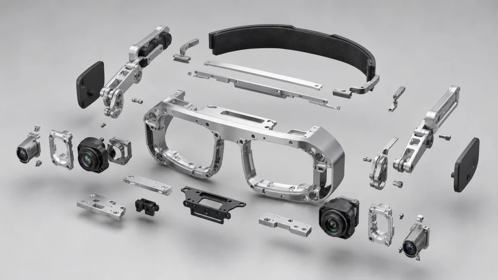
Machining Metal Frames and Mounts Starts With Function
The main frame forms the mechanical coordinate system of a head-mounted display. It locates displays, lenses, outward-facing cameras, eye-tracking sensors, inertial sensors, cooling hardware, facial interfaces, and head-strap attachments. Smaller VR headset mounts may carry one component, yet their error can still propagate into calibration or user comfort.
Each feature has a different mechanical priority. A camera seat needs stable position and angle. A lens carrier needs repeatable spacing and low distortion. A hinge boss must resist repeated torque. A facial-interface rail must distribute pressure without creating a sharp local load. Cable channels require clearance and edge control. Antenna regions may need less metal or a controlled gap in the conductive structure.
Engineers should map how headband tension, hinge motion, impact, thermal growth, and assembly screws travel through the frame. Ribs and bosses can then support sensitive features directly, while low-load areas can be pocketed for mass reduction.
Materials for Machining Metal Frames and Mounts
Material selection balances density, yield strength, corrosion behavior, thermal response, surface finish, procurement, and machining risk. A 2026 peer-reviewed comparison listed headset weights from 515 g to 850 g with headstraps; its three inside-out systems used four or five integrated tracking cameras. Structural mass and sensor support must therefore be considered together.
| Material | Approx. density | Manufacturing strengths | Typical headset role |
|---|---|---|---|
| 6061-T6 aluminum | 2.70 g/cm³ | Good machinability, corrosion resistance, and anodizing response | Main frames, camera bridges, housings, development builds |
| 7075-T6/T651 aluminum | 2.81 g/cm³ | Higher yield strength with aluminum-like weight | Compact hinges, highly loaded bosses, thin structural members |
| AZ31B magnesium | 1.77 g/cm³ | Very low density and useful stiffness-to-mass ratio | Weight-critical internal frames with controlled finishing |
| Ti-6Al-4V titanium | 4.43 g/cm³ | High strength, fatigue resistance, and compact load capacity | Hinge pins, threaded interfaces, premium load-bearing mounts |
| 304 stainless steel | 8.00 g/cm³ | Wear resistance, durable threads, and useful counterweight mass | Inserts, pivots, latch parts, localized balance weights |
6061 often provides the most practical baseline. A move to 7075 helps where yield strength permits a smaller section, although its elastic modulus remains close to 6061. Magnesium needs fire-safety, chip-handling, corrosion, and coating planning. Titanium and stainless steel usually work best as localized elements. Confirm final values against the specified alloy form, temper, and supplier data.
Design Features That Make Headset Frames Machinable
Good AR headset CNC machining begins before toolpaths exist. The CAD model should give cutters access, give fixtures reliable contact, and give the finished part enough structure to survive unclamping. BOONA CNC machining service is relevant when a frame combines precision bores, contoured surfaces, multiple mounting faces, and cosmetic requirements.
Walls, Ribs, and Internal Corners
Uniform wall sections reduce abrupt stiffness changes and make thermal behavior easier to predict. Long walls below roughly 1 mm deserve an early process review because aspect ratio, alloy condition, and unsupported length can matter more than nominal thickness.
Ribs should connect optical or sensor bosses to the primary load path. Large internal radii allow stiffer tools, reduce chatter, and shorten cycle time. Tiny radii should remain only where assembly clearance requires them.
Threads and Interfaces
Repeatedly serviced joints benefit from threaded inserts, steel bushings, or sufficient engagement length. Dowel holes should control location while screws provide clamp force.
Designers should also reserve gripping stock or sacrificial tabs outside cosmetic and functional zones. Without a planned workholding strategy, the machinist may have to clamp a thin finished wall or add an avoidable setup, increasing both deformation risk and datum-transfer error.
Controlling Thin Walls, Residual Stress, and Workholding
The main risk in thin-wall aluminum machining is movement across the full process, including roughing, unclamping, finishing, anodizing, and final assembly. A billet can release residual stress as most of its volume disappears. Cutting heat, uneven stock removal, aggressive clamping, and a long unsupported tool can add more distortion.
A stable process roughs the frame symmetrically, leaves consistent finishing stock, and alternates material removal around opposing walls. Semi-finishing lets movement appear before critical bores and mounting faces receive final cuts. For a broad camera bridge, 0.2 to 0.5 mm of finishing stock may be a discussion range, though geometry and alloy condition must drive the plan.
Soft jaws, vacuum fixtures, expanding mandrels, or purpose-built nests should support load paths without forcing the part flat. Restrained and free-state inspection can expose fixture-induced error. For curved frames with features on several faces, BOONA 5-axis CNC machining services can reduce datum transfers and improve tool access. Five-axis motion still requires sound fixturing and a controlled sequence.
Pro Tip: Add a drawing note that identifies which flatness and position requirements apply in the free state, after finishing, and at the specified assembly torque. That distinction prevents inspectors from accepting a constrained part that moves out of tolerance after release.
Datum Strategy for Tracking Hardware
Reliable optical sensor alignment starts with functional datums that reproduce the assembled coordinate system. A useful scheme might define the display or lens interface as primary datum A, a central locating bore or rail as datum B, and a lateral clocking feature as datum C. Camera seats, IMU pads, and calibration targets can then reference the same framework.
True position and profile controls usually communicate function better than tight plus/minus dimensions scattered across the print. An illustrative camera bridge could call for a 0.05 mm positional zone relative to A|B|C while allowing looser tolerance on exterior pockets. The correct value must come from the optical error budget, calibration range, assembly compliance, and field-of-view model.
Angular error deserves equal attention because a small tilt becomes a larger spatial offset as working distance increases.
Metrology should match the feature. A CMM can verify datums, bores, and pads. Optical measurement can assess small edges or fiducials, while a functional gauge can reproduce the mating assembly.
A 2023 NIST report on AR evaluation found inconsistent methods across devices and underuse of eye-tracking metrics. That reinforces a practical rule: dimensional inspection should feed a device-level calibration test rather than serve as the final proof by itself.
Thermal, Wireless, and Surface-Finish Requirements
Metal frames can spread heat away from processors and displays, but they can also move optical components as temperature changes. Aluminum expands roughly 23 µm/m·°C, so a 100 mm sensor span changes by about 0.046 mm across a 20 °C temperature rise if unconstrained.
Designers should place heat sources, compliant joints, and critical datums so predictable expansion does not rotate cameras or shift the lens relationship.
Conductive frames also influence antennas, grounding, and electromagnetic compatibility. RF engineers should define antenna keep-out zones before mechanical pocketing is frozen. Bare contact pads may be needed for grounding, while insulating breaks can interrupt unwanted current paths. Fastener interfaces require a clear plan for coatings and electrical continuity.
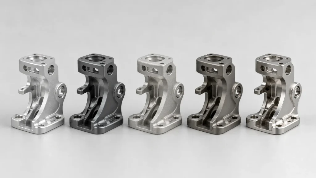
Finishing affects optical behavior and dimensions. Matte black surfaces can suppress internal reflections around cameras, yet blasting may soften edges and change cosmetic texture. Type II anodizing commonly falls in a thinner decorative range, while Type III hard anodizing is thicker and more wear focused.
Critical bores, grounding pads, threads, and precision seats may require masking or pre-compensation. The drawing should state the finish standard, color or gloss criteria, masked zones, and whether dimensional requirements apply before or after coating. A golden sample helps align cosmetic expectations during pilot production.
Real-World Example: A Surgical AR Headset Mount
A 2025 peer-reviewed evaluation of an immersive surgical AR headset provides a useful design case. The DISCOVER study reported an approximately 500 g headset, a cable about 5 m long, and surgeon comments about neck strain and occasional tether restriction. All surgeons learned the head-gesture controls after roughly 10 to 15 minutes, isolating wearability as the mechanical concern.
For a machined brow frame in a comparable ophthalmic system, grams located forward of the head generate more neck moment than mass near the support band. A camera bridge should use pockets away from datum bosses, short load paths around optical seats, and cable anchoring that transfers tether forces into the head support.
A separate 2022 ergonomics paper proposed a total headset target below 350 g for surgical navigation. The research team’s own 840 g prototype did not achieve that target, further demonstrating the difficulty of combining optical hardware, structural support, and long-duration wearability.
Neither study publishes machining tolerances or frame alloy, so those manufacturing decisions remain an engineering inference. The example still connects a documented failure mode, neck strain, to measurable design inputs: total mass, center of mass, cable force path, adjustment torque, and optical stability.
From Headset Prototype to Production
Early prototypes should answer structural questions quickly. An as-machined 6061 frame can reveal assembly access, headband load paths, thermal contact, cable routing, and sensor-calibration behavior without adding cosmetic-finish variables. Teams should record free-state geometry before assembly, apply defined screw torque, and repeat calibration after thermal and motion tests.
The engineering-validation phase should use the intended alloy, temper, inserts, and surface finish. This stage tests coating allowance, wear at hinges, RF effects, repeatable optical alignment, drop or shock response, and user comfort. Where several angled camera or hinge features share a datum system, a single-setup strategy may reduce accumulated repositioning error.
Pilot production then validates repeatability. Freeze stock form, fixture references, tool-access assumptions, inspection routines, and cosmetic criteria. Track critical-to-function dimensions with actual measurement data rather than checking only pass or fail. A process-capability study becomes meaningful once the machining route and measurement method are stable.
Changes in billet source, temper, heat treatment, coating supplier, or workholding should trigger review because each can alter distortion or finish. This staged plan preserves learning while giving purchasing and quality teams a controlled route toward larger quantities.
Inspection Plan and RFQ Checklist
An RFQ should explain how the frame functions, how it will be assembled, and how acceptance will be judged. A STEP file alone rarely captures that intent. Include a dimensioned drawing with datum references, critical-to-function characteristics, coating notes, and the inspection state. Add the mating-component model when collision, access, or load transfer depends on surrounding hardware.
Provide these details before quoting:
- Alloy, temper, stock-form preference, and material-certification needs
- Annual volume, first-build quantity, and expected design revisions
- Primary, secondary, and tertiary datums tied to assembly function
- Optical or sensor features, calibration range, and critical angular relationships
- Screw sizes, inserts, tightening sequence, and assembly torque
- Free-state versus restrained inspection requirements
- Surface-finish standard, cosmetic zones, masking, gloss, and color controls
- RF keep-outs, grounding pads, thermal-interface areas, and cleanliness needs
- Required reports, such as CMM results, material certificates, or first-article records
Device validation should also reflect intended use. ISO/IEC 5927:2024 covers safe AR and VR setup and use, including physical head-mounted displays and visual-stimulus considerations. The ISO website lists it as the current published first edition.
Mechanical acceptance therefore belongs inside a broader plan that includes fit, calibration, thermal behavior, movement, and safe user exposure.
FAQs
What metal is best for an AR or VR headset frame?
6061-T6 balances mass, machinability, corrosion resistance, and finish quality. Use 7075 where higher yield strength enables a smaller section. Magnesium, titanium, and stainless steel suit specialized requirements.
How thin can a CNC-machined aluminum headset frame be?
No universal minimum applies. Thickness depends on span, ribs, temper, tool reach, workholding, finish, and allowed deformation. Long walls near or below 1 mm need early DFM review.
Does 5-axis machining improve headset accuracy?
It can reduce setups and datum transfers while improving access to angled camera seats and hinge bores. Accuracy still depends on calibration, fixturing, thermal control, and inspection.
Which tolerances matter most on a headset frame?
Prioritize features locating displays, lenses, tracking cameras, IMUs, hinges, and facial interfaces. Define them from functional datums. Cosmetic pockets and clearance surfaces can often use broader tolerances.
Should headset frames be inspected before or after anodizing?
Plan critical dimensions for the finished condition and retain pre-finish records where useful. Because anodizing affects bores, threads, grounding points, and fits, the drawing should identify masking and inspection stage.
What files should accompany a headset-frame RFQ?
Send 3D CAD, a controlled drawing, material and finish specifications, quantities, mating geometry, torque, and inspection requirements. Identify optical datums, RF keep-outs, thermal interfaces, and cosmetic surfaces.
Conclusion
Machining metal frames and mounts for AR and VR headsets requires material, geometry, process sequence, and verification to work around the finished device. The strongest design keeps camera and optical datums connected by short, stiff load paths, removes mass from low-stress regions, anticipates free-state distortion, and accounts for coating, heat, RF behavior, and assembly torque.
A well-dimensioned drawing then gives manufacturing and quality teams the same definition of success.
If your headset frame combines thin walls, angled sensor seats, curved cosmetic surfaces, or finish-sensitive fits, send the 3D model and controlled drawing for a manufacturability review. BOONA can assess material choice, datum logic, tool access, workholding, and coating allowances through its aluminum CNC machining service. No minimum order quantity is required, and each quote includes a complimentary DFM review. Send your CAD to start the technical review.


