
“6061 aluminum, anodized” fits in a drawing note, yet leaves a supplier to guess which surfaces must remain conductive, whether precision bores are sized before or after coating, and how a thin plate should be supported during inspection. Those omissions change both the manufacturing route and the quotation.
Machining Aluminum Parts for Semiconductor Equipment works best when the specification connects stock condition to geometry, surface function, and the delivered state. Define the exposure first. Choose alloy and temper against that duty, plan material removal around distortion, and specify finishing boundaries and inspection conditions.
A wafer-handling bracket and a process-facing gas distributor can share an alloy designation while requiring very different controls.
Machining Aluminum Parts for Semiconductor Equipment: Where It Fits
Structural, Motion, and Thermal Components
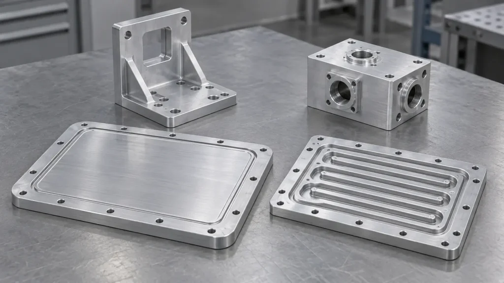
Aluminum can suit equipment frames, inspection-stage plates, sensor mounts, and wafer-handling supports where moving mass, machinability, and heat transfer influence the design. Precision aluminum machining also allows locating features and mounting interfaces to share a controlled datum structure.
The useful question is what each surface does. A mounting face establishes alignment. A thermal contact face transfers heat through its interface. A threaded boss carries assembly loads. Assigning the same roughness or tolerance to all three can add work without improving the equipment.
For moving assemblies, include the load path and mounting arrangement in the design review. Removing material reduces mass, but the remaining geometry must still support the required alignment.
Vacuum and Process-Exposed Components
Aluminum chamber components, gas-distribution hardware, and process-adjacent shields require a separate exposure review. Identify contact with process gases, plasma, cleaning chemistry, or elevated temperature before approving an alloy and treatment.
A material suitable for an external instrument bracket may be inappropriate inside a particular process chamber. Likewise, anodizing alone cannot establish compatibility with every plasma or cleaning recipe.
Separate structural suitability from process approval in the RFQ. The equipment designer must define the operating environment and acceptance requirements.
Selecting the Alloy, Temper, and Starting Stock
Specify More Than an Alloy Number
An alloy designation leaves important purchasing decisions unresolved. Include the temper, product form, material specification, and required documentation. Where orientation affects a critical feature, identify the stock direction on the manufacturing plan.
For rolled plate, 6061-T651 incorporates stress relief by stretching. That processing reduces residual stress; substantial or uneven material removal can still change the finished shape. A generic “6061” callout does not define the same starting condition.
Avoid adding an unspecified heat-treatment step simply to address movement. Any treatment must remain compatible with the required final temper and properties.
Match the Stock Route to the Component
The following purchasing framework compares possible routes. It does not establish interchangeable material grades.
| Starting stock | Potential application | Main decision point | Evidence to request |
|---|---|---|---|
| 6061-T651 rolled plate | Pocketed bases and mounting plates | Residual stress and released geometry | Material certification and agreed flatness inspection |
| Approved aluminum bar or extrusion | Compact brackets and repeated profiles | Product-form-specific temper and stock direction | Stock identification and finished-feature inspection |
| Precision cast tooling plate | Non-process-exposed fixtures | Strength, coating response, and customer approval | Product-specific data and substitution approval |
| Approved higher-strength wrought alloy | Load-limited supports | Corrosion, finish compatibility, and joining requirements | Design approval and material traceability |
A precision-faced blank can reduce initial surfacing work. Its incoming flatness does not guarantee the condition after pocketing or coating.
Before quoting a substitution, check whether the drawing specifies a material for mechanical performance, process compatibility, or an existing equipment qualification. These reasons lead to different approval paths.
Controlling Distortion, Burrs, and Thermal Movement
Thin Walls and Deep Pockets
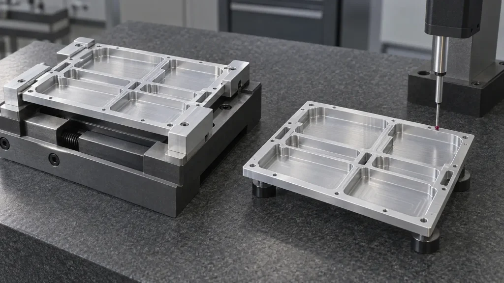
Pocketing changes the balance of material and residual stress. Cutting forces can also deflect unsupported walls, while clamping can temporarily hold a flexible plate in a shape it will not retain after release.
BOONA published machining guidance on thin-wall workholding emphasizes appropriate support and control of clamping distortion. Applied to an equipment plate, the decision rule is straightforward: if the drawing calls for free-state flatness, clamping the plate flat during measurement conceals the condition being assessed.
Plan roughing, release checks, and finishing around the remaining stiffness. Balanced removal can be worth evaluating, although geometry and access may prevent a fully symmetric sequence.
A 2026 university study of thin-wall milling strategies illustrates the process sensitivity. Section 3.2 and Figure 9 in the original paper report approximately 70% lower flatness deviation for a hybrid strategy at 900 m/min compared with a “Christmas tree” strategy at 600 m/min, for both tested alloys.
The experiment used aerospace-oriented 2024-T351 and 7050-T7451 specimens. Both strategy and cutting speed changed, so the result cannot be attributed to toolpath alone. This was not a BOONA project and does not establish BOONA capability or a tolerance for semiconductor parts. The engineering inference is to evaluate machining sequence and released geometry together.
Burrs at Passage Intersections
A visible external edge is easier to inspect than a burr inside intersecting drilled passages. Plan how the tool, deburring method, and inspection method will reach each intersection.
If a hole controls flow or locates a component, aggressive deburring can alter the functional edge. Specify the permitted edge condition before selecting the removal method. “Deburr all edges” leaves too much interpretation for a metering feature.
Temperature-Sensitive Alignment
Separate dimensions measured after machining from dimensions required during operation. An aluminum carrier attached to a dissimilar-material assembly can change alignment as temperatures change.
For critical interfaces, identify the inspection temperature, mounting constraint, and relevant operating condition. Tighter room-temperature machining limits alone cannot resolve an undefined thermal arrangement.
Specify Surface Treatments by Function
Anodizing, Masking, and Finished Dimensions
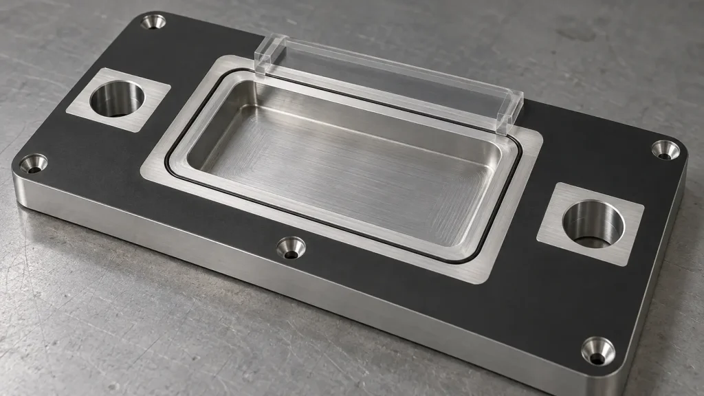
Surface treatment affects more than appearance. Coating growth changes fits, while insulating oxide can conflict with an intended electrical contact. Masking boundaries therefore belong in the drawing package.
BOONA machining guidance also recommends discussing tight-fitting features before anodizing. The practical decision is whether a bore needs a continuous coating, an exposed metal fit, or a separately approved finishing operation. Reaming a coated bore to restore size can remove the very layer the design requires.
Review the available surface finishing options against each surface’s function. A general finishing menu does not establish compatibility with a semiconductor process.
Build a Surface-by-Surface Acceptance Matrix
Instead of applying one blanket finishing note, assign requirements to functional zones. This is a drawing-review framework, not a standardized classification.
| Surface or feature | Functional requirement | Drawing decision | Acceptance evidence |
|---|---|---|---|
| Locating bore | Repeatable fit and position | Finished size and coating condition | Measurement after the specified finishing stage |
| Sealing land | Controlled gasket contact | Flatness, texture, and permissible damage | Surface inspection in the agreed support condition |
| Electrical contact pad | Required conductive interface | Mask boundary and permitted treatment | Visual verification and specified electrical checks |
| Process-facing surface | Compatibility with exposure | Approved treatment and contamination limits | Customer-defined finishing and cleanliness records |
| Internal passage | Unobstructed, clean flow path | Burr limits and cleaning access | Agreed internal inspection or functional test |
Pro Tip: Mark coating exclusions and final-size inspection requirements on the same drawing revision. Separate emails about masking can leave the machinist, finisher, and inspector working to different interpretations.
For a sealing face, also define whether appearance limits apply before protective packaging or at receipt. An otherwise acceptable surface can acquire handling damage between those stages.
Cleaning, Inspection, and Protected Delivery
Separate Surface Finish from Cleanliness
A low roughness reading does not demonstrate removal of machining fluid, embedded debris, or cleaning residue. Conversely, a clean surface can still have unsuitable geometry.
The current published edition, ISO 14644-9:2022, addresses assessment of surface particle cleanliness. Its public scope excludes process-specific surface suitability requirements and cleaning procedures. Referencing it therefore does not establish a cleaning recipe or prove that a component is suitable for a particular semiconductor process.
Specify what contamination matters and how acceptance will be checked. Airborne particles, removable surface particles, and chemical residues represent different questions.
Define the Condition Covered by Each Report
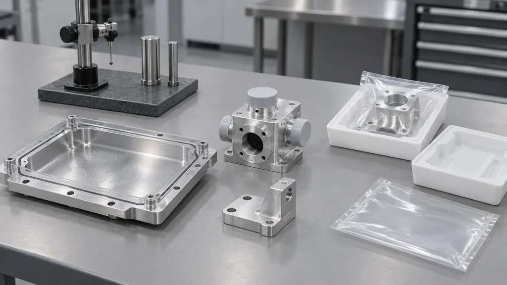
Agree whether dimensional inspection occurs as machined or after finishing. Identify the support condition for flexible parts and protect the datum surfaces used during measurement.
Cleaning and inspection also need an order. If a final dimensional check requires substantial handling, decide how the part will regain its agreed delivery condition afterward.
The delivery package should connect the part revision to its material record, inspection results, and any required finishing documentation. Define protection for threads, contact faces, and open passages.
A leak test, when specified, applies to the tested configuration under stated conditions. A machined part, material certificate, or generic cleanliness statement cannot establish the performance of a complete chamber assembly.
Machining Aluminum Parts for Semiconductor Equipment: Cost and RFQ Planning
What Changes Manufacturing Cost
Part weight gives an incomplete picture of cost. Thin remaining sections may require more support and intermediate checks. Inaccessible passage intersections add deburring and inspection work. Selective finishing introduces masking and coordination between operations.
Compare quotations at the same delivery state. A price for an as-machined plate cannot be compared directly with a price that includes selective anodizing, final inspection, cleaning, and protected packaging.
Application Example: Angular Alignment in an Implantation Holder
A 2024 study of high-energy implantation in silicon carbide provides a concrete equipment example. Section 2.2.1, “Channeling with holder,” on page 3 of the original paper describes an aluminum sample holder machined for an implantation chamber.
That section reports milling-machine angular precision of 0.1°, compared with an estimated critical channeling angle of 0.08° for the 20 MeV implantation condition. Machining accuracy and sample-mounting errors contributed to beam misalignment. Figure 3 in the paper shows the holder.
The issue was an angular error budget spanning the machined fixture and its installation. The engineering inference is to define how a locating surface transfers orientation into the operating setup, including the mounting method.
This was not a BOONA project and does not establish BOONA capability. The cited passage does not identify the holder’s aluminum alloy or confirm CNC machining. Its angular values are specific to the experiment, not general semiconductor machining tolerances.
What Buyers Should Submit
An actionable RFQ should include:
- Released CAD and a drawing with revision control.
- Alloy, temper, stock form, and substitution restrictions.
- Functional datums, critical fits, and inspection support conditions.
- Exposure conditions and approved surface treatments.
- Masking zones and dimensions required after finishing.
- Cleanliness criteria, documentation, packaging, and order quantity.
If an assembly controls alignment, include the mating arrangement. A drawing of the isolated part may omit the interface that determines whether its tolerances are useful.
FAQs
What Aluminum Alloy Is Best for Semiconductor Equipment Parts?
Selection depends on function and exposure. Approved 6061 products can suit many mechanical components, while process-facing parts need additional compatibility review. Higher strength, a familiar alloy name, or an anodized surface alone cannot establish suitability.
Is 6061-T651 Appropriate for Precision Equipment Plates?
It can be an appropriate starting point when the design accepts that alloy and plate condition. Stretching reduces residual stress, but the machining sequence, remaining wall geometry, and inspection restraint still influence the finished result.
Why Can an Aluminum Plate Move After Pocketing?
Removing material changes the internal stress balance and reduces stiffness. Cutting loads and fixture forces can introduce additional shape differences. Review released geometry and support conditions before treating every deviation as a machine-positioning problem.
Should Every Aluminum Semiconductor Component Be Anodized?
No. Some surfaces need electrical contact, controlled fits, or a different approved treatment. Process exposure may impose additional restrictions. Specify treatment and masking by functional zone rather than assuming one finish should cover the entire component.
Must These Parts Be Machined Inside a Cleanroom?
The operating environment does not automatically define the machining environment. Manufacturing, cleaning, verification, and packaging requirements depend on the customer specification. Identify the required delivery condition and approved controls instead of relying on a generic “cleanroom-ready” claim.
What Should an Aluminum Machining RFQ Include?
Send the CAD model, controlled drawing, material condition, quantity, and finishing requirements. Add the inspection state and contamination criteria. Identify critical mating parts or assembly conditions when they determine alignment, sealing, or the usefulness of a dimensional tolerance.
Conclusion: Specify the Delivered Condition
Machining Aluminum Parts for Semiconductor Equipment requires coordinated decisions about stock, geometry, finishing, and verification. Begin with the component’s exposure and functional interfaces. Then define when each requirement applies: after machining, after treatment, or in the specified assembly condition.
Keep procurement focused on those acceptance decisions. A broad alloy callout or a blanket anodizing note leaves several costly assumptions unresolved. Unnecessarily tight limits on low-risk features can consume inspection effort while a decisive masking boundary or unsupported-flatness condition remains unspecified.
For a review of your component, send BOONA the CAD model, drawing, operating context, and required delivery state. BOONA offers no minimum order quantity and a free DFM review. Explore its aluminum CNC machining service to discuss material selection, machining constraints, and the inspection scope before requesting a quotation.


