
Pure copper looks simple until it is on the machine.
It is soft. It conducts heat well. It is not abrasive like stainless steel or titanium. On paper, it should be easy.
Then the cutter touches it.
Instead of clean chips, you get long shiny ribbons. They wrap around the end mill. They drag across the pocket floor. They stick to the flute. Sometimes they form a copper bird’s nest before the operator even has time to stop the cycle.
That is the real headache in CNC machining gummy pure copper. The problem is not only cutting the material. The problem is controlling the chip before it ruins the finish, loads the tool, or leaves burrs everywhere.
This matters a lot for parts like busbars, battery terminals, RF connectors, heat-transfer plates, grounding blocks, and high-conductivity electrical components. These parts often need clean surfaces, reliable dimensions, and low burr levels, not just a rough shape cut from copper stock.
For projects that need custom copper CNC machining, chip control should be planned before programming starts. Once pure copper starts smearing and wrapping, fixing it at the end of the process is usually slower and more expensive.
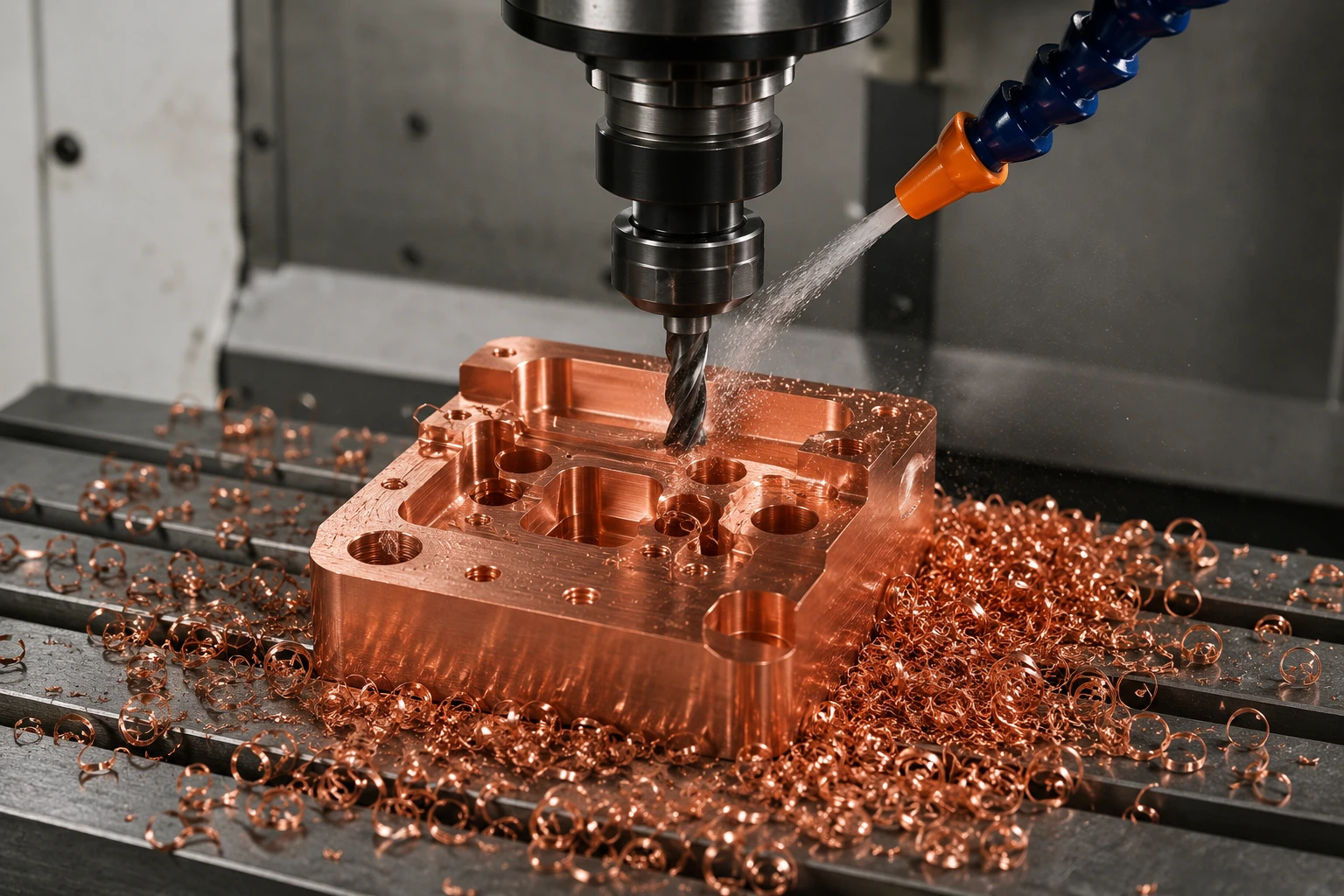
Why Pure Copper Refuses to Break Chips Cleanly
Pure copper does not chip like brass.
Brass usually fractures into smaller, more manageable chips. Pure copper stretches. It bends. It smears. It wants to stay in one long strip if the tool does not force it to shear properly.
That behavior comes from copper’s ductility. C101 and C110 are both high-purity copper grades, and both are known for being “gummy” under the cutting edge. Boona’s pure copper machining content describes the same shop-floor issue: copper tends to smear, form built-up edge, and create burrs when the tool rubs instead of cutting.
In daily machining, the signs are easy to recognize:
| What You See | What It Usually Means |
|---|---|
| Long, hair-like copper ribbons | Feed is too light or chip is too thin |
| Copper stuck to the flute | Heat, adhesion, or poor lubrication |
| Burrs along the edge | Tool pressure is too high or edge is dull |
| Scratches on the finished surface | Chips are being recut |
| Poor pocket finish | Chips are trapped in the cut |
| Sudden size variation | Built-up edge is changing the cutting condition |
A lot of machinists react by slowing the job down. Sometimes that helps. But with pure copper, going slower can also make the cutter rub more. And rubbing is exactly what makes copper smear.
The better goal is this: make a real chip, give it space to leave, and keep it from welding to the tool.
The First Fix Is Usually Feed, Not Speed
When copper forms thin continuous ribbons, the feed is often too light.
That sounds backward because pure copper feels soft. Many programmers get cautious and reduce the feed too much. The cutter then stops biting into the material and starts polishing it. Once that happens, heat builds up at the edge, the copper gets sticky, and chip control gets worse.
For breaking chips machining pure copper, the chip has to be thick enough to curl, move, and separate from the cut.
A practical starting range for carbide milling is below:
| End Mill Size | Starting Chip Load | Practical Note |
|---|---|---|
| 3 mm / 1/8 in | 0.0008–0.0015 in/tooth | Use light engagement and strong chip evacuation |
| 6 mm / 1/4 in | 0.0015–0.0030 in/tooth | Good starting point for pockets and profiles |
| 10 mm / 3/8 in | 0.0025–0.0045 in/tooth | More stable if workholding is rigid |
| 12 mm / 1/2 in | 0.0030–0.0060 in/tooth | Useful for roughing when the setup is solid |
These numbers are not magic. They are starting points. The right value depends on tool geometry, flute count, radial engagement, coolant, machine rigidity, and part shape.
But the principle is important: do not run such a light feed that the tool only rubs the copper.
If the chip is paper-thin and stringy, increase feed slightly before making major changes to the whole program.
Use Sharp, Open, Polished Tools
Pure copper does not forgive a dull tool.
A general-purpose cutter may work for aluminum or mild steel, but in gummy copper it often pushes material instead of slicing it. The result is built-up edge, heat, smearing, and heavy burrs.
For most pure copper milling jobs, I would start with a sharp polished carbide end mill designed for non-ferrous metals. Two or three flutes are usually easier to manage than four flutes because they give the chip more room to escape.
| Tool Choice | Why It Helps Copper |
|---|---|
| Sharp cutting edge | Reduces rubbing and smearing |
| High positive rake | Helps copper shear instead of tear |
| Polished flutes | Reduces chip sticking |
| 2-flute or 3-flute design | Gives long chips more space |
| DLC or diamond-like coating | Helps reduce copper adhesion |
| Separate finishing tool | Keeps final surface away from roughing wear |
The tool should look almost too sharp compared with a steel-cutting tool. Heavy edge prep is usually not your friend here.
This is especially true for C110. If you are also working with C110 parts, the related Boona guide on C110 copper CNC speeds and feeds is a useful internal reference for choosing a safe starting range before fine-tuning chip control.
Give the Chip Somewhere to Go
Chip breaking is partly about cutting parameters, but it is also about space.
Full-width slotting in pure copper is asking for trouble. The cutter is buried, coolant has a hard time reaching the edge, and copper chips have nowhere to go. Once chips pack inside a slot, the tool starts cutting the same chips again. That is when the finish gets scratched and the burrs get worse.
For pocketing and roughing, adaptive clearing or trochoidal milling is usually more stable.
| Toolpath Style | Chip Control Result |
|---|---|
| Full slotting | Highest risk of chip packing |
| Heavy stepover pocketing | Chips can recut and scratch the floor |
| Adaptive clearing | More consistent engagement and better evacuation |
| Trochoidal milling | Helps keep the tool from being buried |
| Roughing + finishing pass | Better finish and easier burr control |
A common roughing setup is 10–25% radial engagement with enough axial depth to make a useful chip. This keeps tool pressure controlled while giving chips room to leave the cut.
That also helps explain why part design matters. Deep narrow slots, tight inside corners, and closed pockets make copper much harder to machine. On parts like electrical blocks, copper heat sinks, and battery terminals, a small increase in corner radius or slot width can make the job far more stable.
For more design and manufacturing context, this topic fits naturally with Boona’s page on CNC machining pure copper custom parts.
Coolant Is Not Just Cooling — It Is Chip Management
In pure copper, coolant has three jobs.
It cools the cut.
It lubricates the edge.
It pushes chips out of the danger zone.
If coolant only hits the top of the toolholder and never reaches the actual cutting edge, it is not doing much. The nozzle direction matters. Air blast direction matters. In pockets, the coolant must help chips leave the cut, not push them deeper into a corner.
| Method | Best Use | Watch Out For |
|---|---|---|
| Flood coolant | General milling, drilling, turning | Must be aimed at the cutting zone |
| High-pressure coolant | Deep holes, turning, grooving | Needs machine support |
| Air blast | Open milling and shallow pockets | No lubrication by itself |
| Mist / MQL | Light cuts and finishing | Limited flushing power |
| Cutting oil | Tapping, reaming, hand finishing | Slower but useful for tool life |
For open milling, a strong air blast can be very effective because it prevents chip recutting. For drilling, air alone is usually not enough. The chip has to come out of the hole, and that usually means coolant, a good peck cycle, or a drill geometry designed for chip evacuation.
Drilling Pure Copper: Do Not Let Chips Pack in the Hole
Drilling is where pure copper can become especially unpleasant.
A milling cutter has open space around it. A drill does not. The chip has to travel up the flute. If it cannot, it packs in the hole, scratches the wall, grabs the drill, or breaks the tool.
For pure copper drilling chip control, use a sharp drill with enough flute space. Parabolic drills are often useful for deeper holes. Through-coolant drills can help when the part geometry and machine allow it.
| Drill Type | Starting Surface Speed | Feed Range | Best Use |
|---|---|---|---|
| HSS drill | 100–250 SFM | 0.001–0.006 in/rev | Short holes, small batches |
| Carbide drill | 200–500 SFM | 0.002–0.010 in/rev | Repeatable holes and production work |
| Parabolic drill | 150–400 SFM | 0.002–0.008 in/rev | Deeper holes and better chip flow |
| Through-coolant drill | Toolmaker recommendation | Toolmaker recommendation | Deep or critical holes |
Peck drilling helps, but too much pecking can also create rubbing. The drill should clear the chip without polishing the same copper wall again and again.
For tight holes, do not expect the drill to do everything. Drill undersize, then ream, bore, or machine the feature if the tolerance matters.
Turning Pure Copper: Use Enough Cut to Make the Chipbreaker Work
On a lathe, pure copper can make very long ribbons because the cut is continuous. A poor setup can create chips that wrap around the part, chuck, tool, or tailstock.
For turning, use inserts made for non-ferrous metals: sharp, polished, positive rake, and with a chipbreaker that actually works in soft materials.
The chipbreaker needs enough feed and depth of cut. If the cut is too light, the chip may never hit the chipbreaker correctly.
| Turning Operation | Surface Speed | Feed | Depth of Cut | Chip Control Tip |
|---|---|---|---|---|
| Rough turning | 350–700 SFM | 0.004–0.012 in/rev | 0.5–2.5 mm | Use enough DOC to curl the chip |
| Finish turning | 500–900 SFM | 0.002–0.006 in/rev | 0.1–0.5 mm | Avoid rubbing with too light a feed |
| Grooving | 200–500 SFM | Tool-dependent | Light to medium | Keep coolant strong and direct |
| Parting | 150–400 SFM | Steady feed | Full cutoff | Keep blade sharp and square |
For turned terminals, pins, sleeves, and conductive shafts, the internal link to CNC turning services fits naturally because chip control is just as important in turning as in milling.
One shop-floor habit helps: do not judge copper turning only by whether the surface looks shiny. Copper can look shiny even when the tool is rubbing. Check the chip shape and the tool edge.
What to Change When the Chips Go Wrong
When copper chips start wrapping, do not change ten things at once. Make one change, watch the chip, then decide.
| Problem | First Thing to Check | Practical Adjustment |
|---|---|---|
| Thin endless ribbons | Feed may be too light | Increase chip load slightly |
| Copper stuck to tool | Adhesion and heat | Add lubrication, use polished tool |
| Chips packing in pocket | Tool is buried | Reduce radial engagement |
| Scratched surface | Chip recutting | Improve flushing or air blast |
| Heavy exit burr | Dull edge or poor exit path | Use sharp tool and add chamfer pass |
| Drill grabbing | Chips trapped in hole | Improve peck cycle or drill geometry |
| Finish changes mid-run | Built-up edge | Stop and inspect the tool |
This troubleshooting approach is more useful than chasing one perfect speed. Pure copper responds to the whole process, not just one number.
A Simple Copper Chip-Control Setup That Usually Works
For many milled pure copper parts, this is a reliable starting approach:
Use a sharp 2-flute or 3-flute polished carbide end mill.
Avoid full slotting when possible.
Start with moderate surface speed.
Keep enough chip load to avoid rubbing.
Use flood coolant or air blast aimed directly at the tool.
Leave stock for a separate finishing pass.
Use a clean finishing tool for the final surface.
Inspect the first part before running the batch.
That setup will not solve every copper job, but it gives the process a good chance. It also reduces the risk of chasing surface finish problems that were actually chip evacuation problems.
For prototype-to-batch copper parts, this is where low-volume manufacturing planning becomes important. A process that works for one prototype may need better chip evacuation, tool life tracking, and inspection control before it can run consistently in a batch. Boona’s low-volume page describes production support from 1 to 10,000 metal or plastic parts, which fits this kind of transition from prototype validation to repeatable production.
Chip Control Also Affects Inspection
Copper chip problems do not end at the machine.
Long chips can scratch cosmetic surfaces. Built-up edge can change dimensions. Burrs can hide on hole exits or pocket edges. Soft copper can also deform during aggressive deburring.
That is why the first article should be checked carefully before the rest of the parts are run. Look at the finish, burrs, edge quality, hole condition, and any contact surfaces that matter electrically or thermally.
For copper parts used in electrical or thermal applications, inspection is not just about size. Surface condition matters too. Boona’s quality control page is a suitable internal link here because copper parts often need both dimensional inspection and visual surface review before shipment.
Final Thoughts
Pure copper is not hard to machine because it is hard. It is hard to machine because it is soft, sticky, and ductile.
To break chips when machining pure copper, do not rely on one trick. Use a sharp positive-rake tool. Keep enough feed to shear the material. Avoid burying the cutter. Aim coolant or air where the chip forms. Give the chip a path out of the cut. Use a separate finishing tool when the surface matters.
Most copper chip problems start small. A little rubbing becomes built-up edge. Built-up edge becomes poor finish. Poor chip evacuation becomes scratches and burrs. By the time the part reaches inspection, the cost has already been added.
A better process starts earlier.
For engineers designing high-conductivity parts, better pure copper chip control means cleaner surfaces, fewer burrs, more stable tolerances, and less rework. And for parts like busbars, heat sinks, battery contacts, RF components, and grounding blocks, that can be the difference between a part that only looks machined and a part that is ready to work.
FAQs
Why does pure copper make long stringy chips during CNC machining?
Pure copper is soft, ductile, and sticky, so it tends to stretch instead of fracture during cutting. If the tool is dull, the feed is too light, or chips cannot escape the cut, copper will often form long ribbon-like chips that wrap around the tool or scratch the part surface.
What is the best way to break chips when machining pure copper?
The best way is to combine a sharp positive-rake tool, enough chip load, controlled radial engagement, and strong coolant or air blast. The goal is to make the copper shear cleanly instead of rubbing. In many cases, increasing feed slightly works better than simply slowing the spindle down.
Should I use a 2-flute or 4-flute end mill for gummy copper?
For most gummy pure copper milling jobs, a 2-flute or 3-flute polished carbide end mill is usually better than a 4-flute tool. Fewer flutes give the long copper chips more room to escape, which helps reduce chip packing, built-up edge, and chip recutting.
What causes built-up edge when machining pure copper?
Built-up edge happens when copper sticks to the cutting edge under heat and pressure. Common causes include dull tooling, poor lubrication, too light of a feed, rough flute surfaces, and poor chip evacuation. Using sharp polished tools, proper coolant, and a real chip load can help reduce this problem.
Is full-width slotting bad for pure copper?
Full-width slotting is often risky in pure copper because chips have very little space to escape. This can lead to chip packing, tool loading, poor finish, and broken tools. Adaptive clearing or trochoidal milling is usually a better strategy for improving pure copper chip control.
How can I improve chip control when drilling pure copper?
Use sharp drills with good flute clearance, apply coolant directly into the hole, and use a peck cycle for deeper holes. For deep or critical holes, parabolic flute drills or through-coolant carbide drills can help remove long copper chips more effectively.
What feed rate helps break copper chips in turning?
In turning, the feed must be high enough to activate the insert’s chipbreaker. If the feed or depth of cut is too light, copper may form continuous ribbons instead of curling and breaking. A sharp polished positive-rake insert designed for non-ferrous metals is usually the best starting point.
How do I reduce burrs when machining gummy pure copper?
Burrs can be reduced by using sharp tools, avoiding excessive rubbing, controlling exit paths, and adding a light finishing or chamfering pass. Good chip evacuation also matters because recut chips can drag across edges and make burrs worse.


